

Half Bridge with Single PWM Input
- Rajkumar Sharma
- 59 Views
- easy
- Tested
- SKU: EL148984
- Quote Now
- 0 Likes


This is a Half-bridge module based on the LM5104 chip, which is a high-voltage gate driver. This High-Voltage Gate Driver is designed to drive both the high-side and the low-side N-channel MOSFETs in a synchronous buck configuration. The floating high-side driver can work with supply voltages up to 100V. The high-side and low-side gate drivers are controlled from a single PWM input. Each state change is controlled adaptively to prevent shoot-through issues. In addition to the adaptive transition timing, an additional delay time can be added, proportional to an external setting resistor. An integrated high-voltage diode is provided to charge the high-side gate drive bootstrap capacitor. A robust level shifter operates at high speed while consuming low power and providing clean level transitions from the control logic to the high-side gate driver. Undervoltage lockout is provided on both the low-side and the high-side power rails.
The user must take care of the following:
- Bootstrap capacitor value depends on the input frequency
- Choose the right MOSFET as per Load Current/Voltage
- Choose the Right Value for delay resistor R4-RT, Depending on MOSFET Gate Capacitance. Refer to Datasheet for more info.
Features
- Power Supply Load up to 48V (Limited Due to Capacitor Volt)
- Power Supply Gate Driver 9V to 14V DC
- Load Up to 5Amps (Higher with Cooling Fan)
- Drives Both a High-Side and Low-Side N-Channel MOSFET
- Adaptive Rising and Falling Edges with Programmable
- Additional Delay
- Under Voltage Threshold 7V
- Adjustable Delay 90 to 200nS (RT(R4) 10K to 100K)
- Operating Frequency Input up to 1000Khz
- Single Input Control
- Bootstrap Supply Voltage Range up to 118-V DC
- Fast Turnoff Propagation Delay (25 ns Typical)
- Drives 1000-pF Loads With 15-ns Rise and Fall Times
- Supply Rail Under Voltage Lockout
- On Board Power LED
- Screw Terminals for Load Supply and Load
- Header Connector for Input signal and Gate Driver Supply
- 5mm x 4 PCB Mounting Holes
- PCB Dimensions 44.45 x 29.53 mm
Applications
- Current Fed Push-Pull Power Converters
- High Voltage Buck Regulators
- Active Clamp Forward Power Converters
- Half-Bridge and Full-Bridge Converters
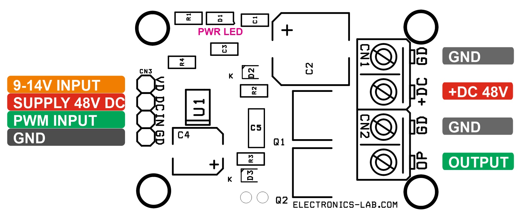
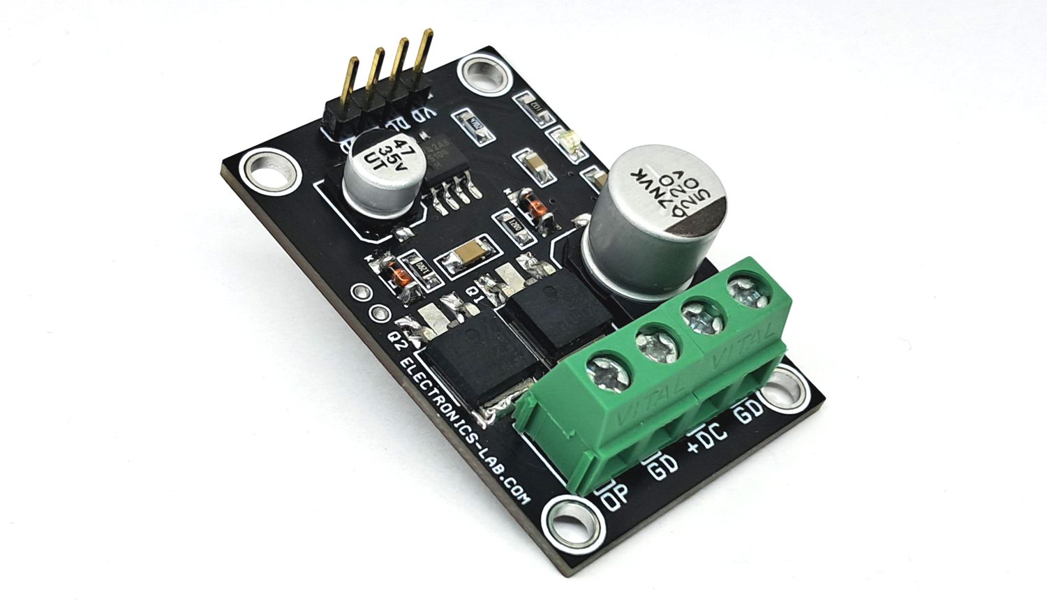
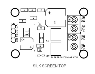
Connections
- CN1: Pin 1 Power Supply Load 48V DC, Pin 2 = GND
- CN2: Pin 1 Output, Pin 2 = GND
- CN3: Pin 1 VDD 9V to 14V, Pin 2 = Load Power Supply, Pin 3 = PWM Input, Pin 4 = GND
- D1: Power LED
Schematic
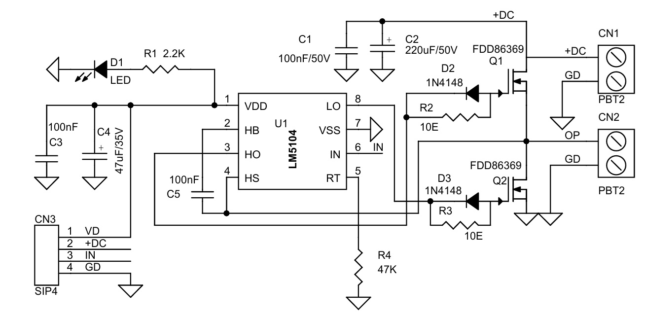
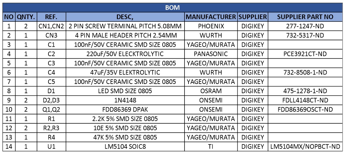
Parts List
| NO | QNTY. | REF. | DESC, | MANUFACTURER | SUPPLIER | SUPPLIER PART NO |
|---|---|---|---|---|---|---|
| 1 | 2 | CN1,CN2 | 2 PIN SCREW TERMINAL PITCH 5.08MM | PHOENIX | DIGIKEY | 277-1247-ND |
| 2 | 1 | CN3 | 4 PIN MALE HEADER PITCH 2.54MM | WURTH | DIGIKEY | 732-5317-ND |
| 3 | 1 | C1 | 100nF/50V CERAMIC SMD SIZE 0805 | YAGEO/MURATA | DIGIKEY | |
| 4 | 1 | C2 | 220uF/50V ELECKTROLYTIC | PANASONIC | DIGIKEY | PCE3921CT-ND |
| 5 | 1 | C3 | 100nF/50V CERAMIC SMD SIZE 0805 | YAGEO/MURATA | DIGIKEY | |
| 6 | 1 | C4 | 47uF/35V ELEKTROLYTIC | WURTH | DIGIKEY | 732-8508-1-ND |
| 7 | 1 | C5 | 100nF/50V CERAMIC SMD SIZE 0805 | YAGEO/MURATA | DIGIKEY | |
| 8 | 1 | D1 | LED SMD SIZE 0805 | OSRAM | DIGIKEY | 475-1278-1-ND |
| 9 | 2 | D2,D3 | 1N4148 | ONSEMI | DIGIKEY | FDLL4148CT-ND |
| 10 | 2 | Q1,Q2 | FDD86369 DPAK | ONSEMI | DIGIKEY | FDD86369OSCT-ND |
| 11 | 1 | R1 | 2.2K 5% SMD SIZE 0805 | YAGEO/MURATA | DIGIKEY | |
| 12 | 2 | R2,R3 | 10E 5% SMD SIZE 0805 | YAGEO/MURATA | DIGIKEY | |
| 13 | 1 | R4 | 47K 5% SMD SIZE 0805 | YAGEO/MURATA | DIGIKEY | |
| 14 | 1 | U1 | LM5104 SOIC8 | TI | DIGIKEY | LM5104MX/NOPBCT-ND |
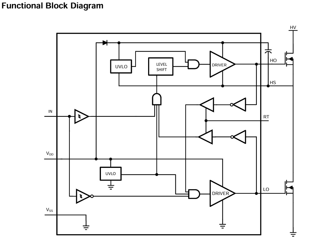
Block Diagram
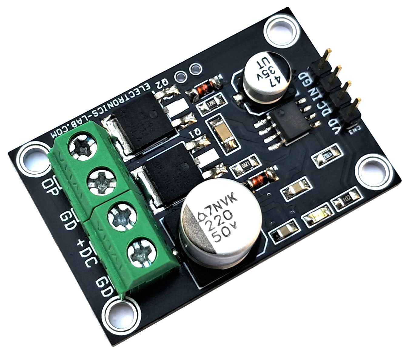
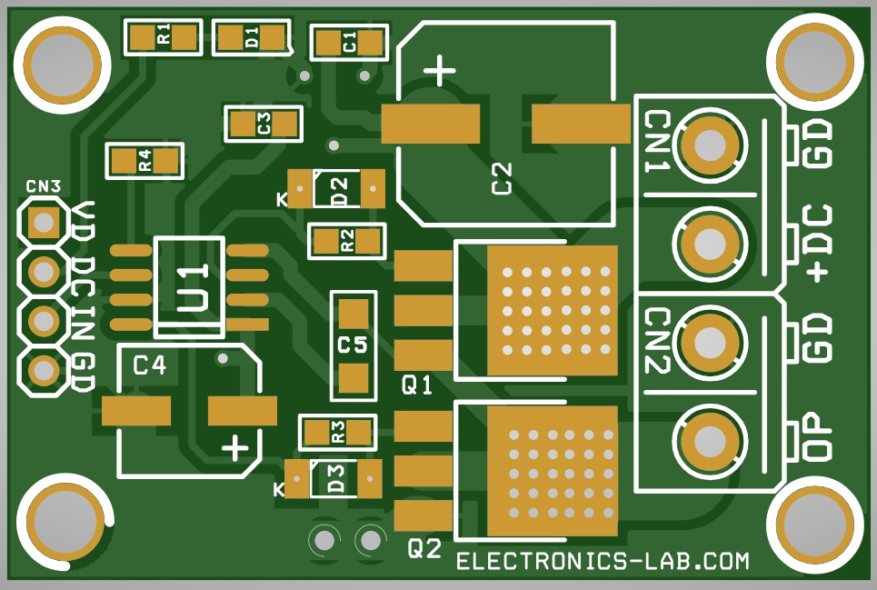
Connections
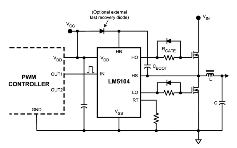
Typical Application
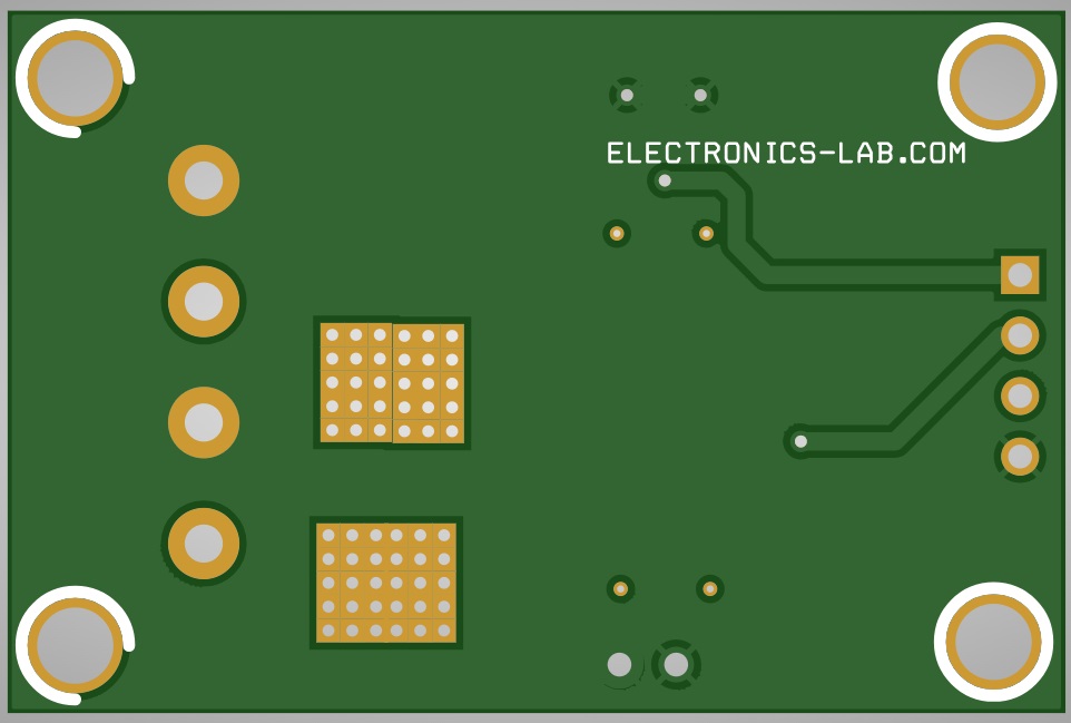
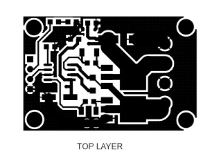
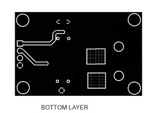
Gerber View
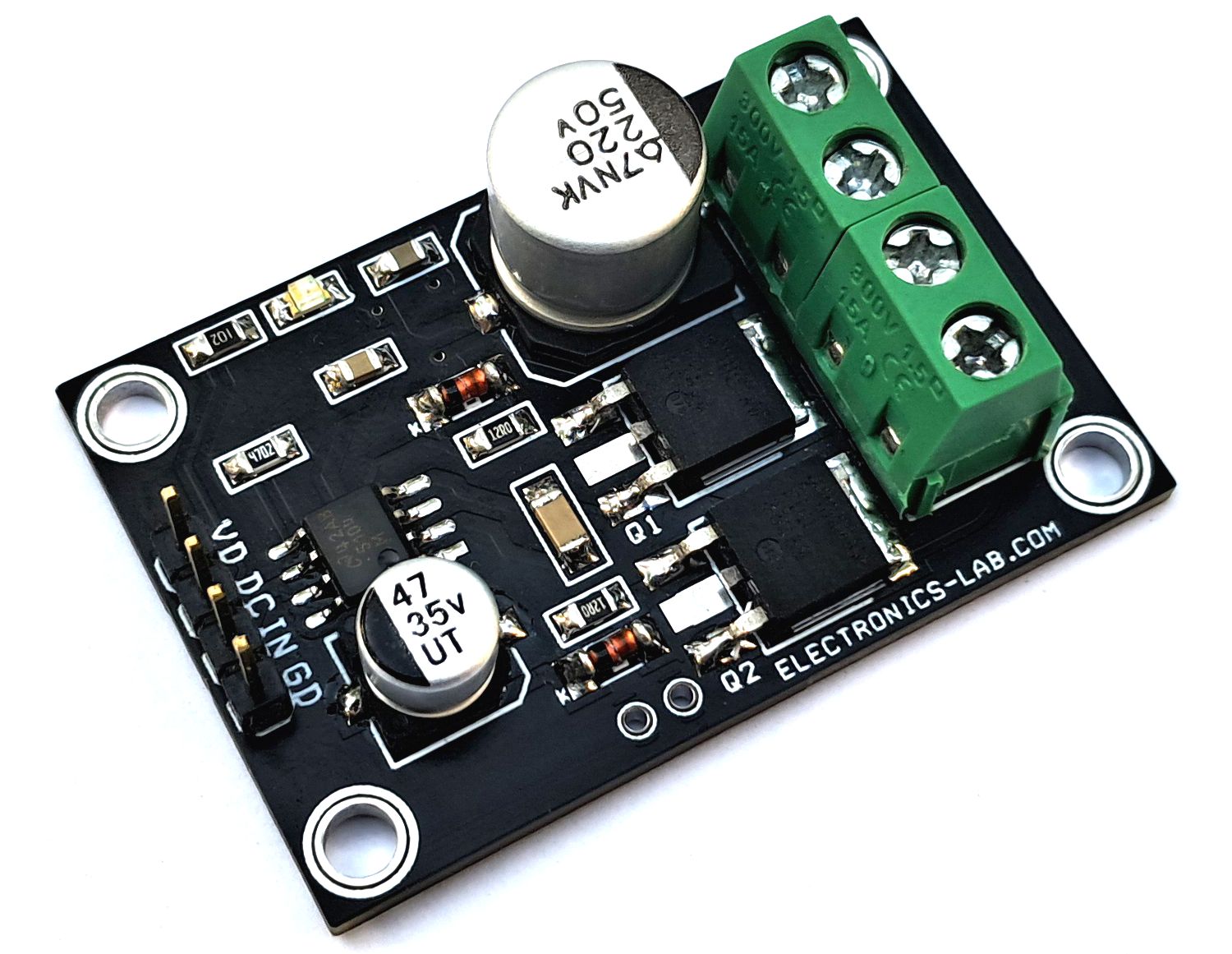
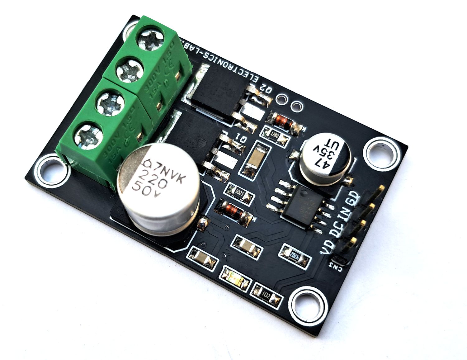
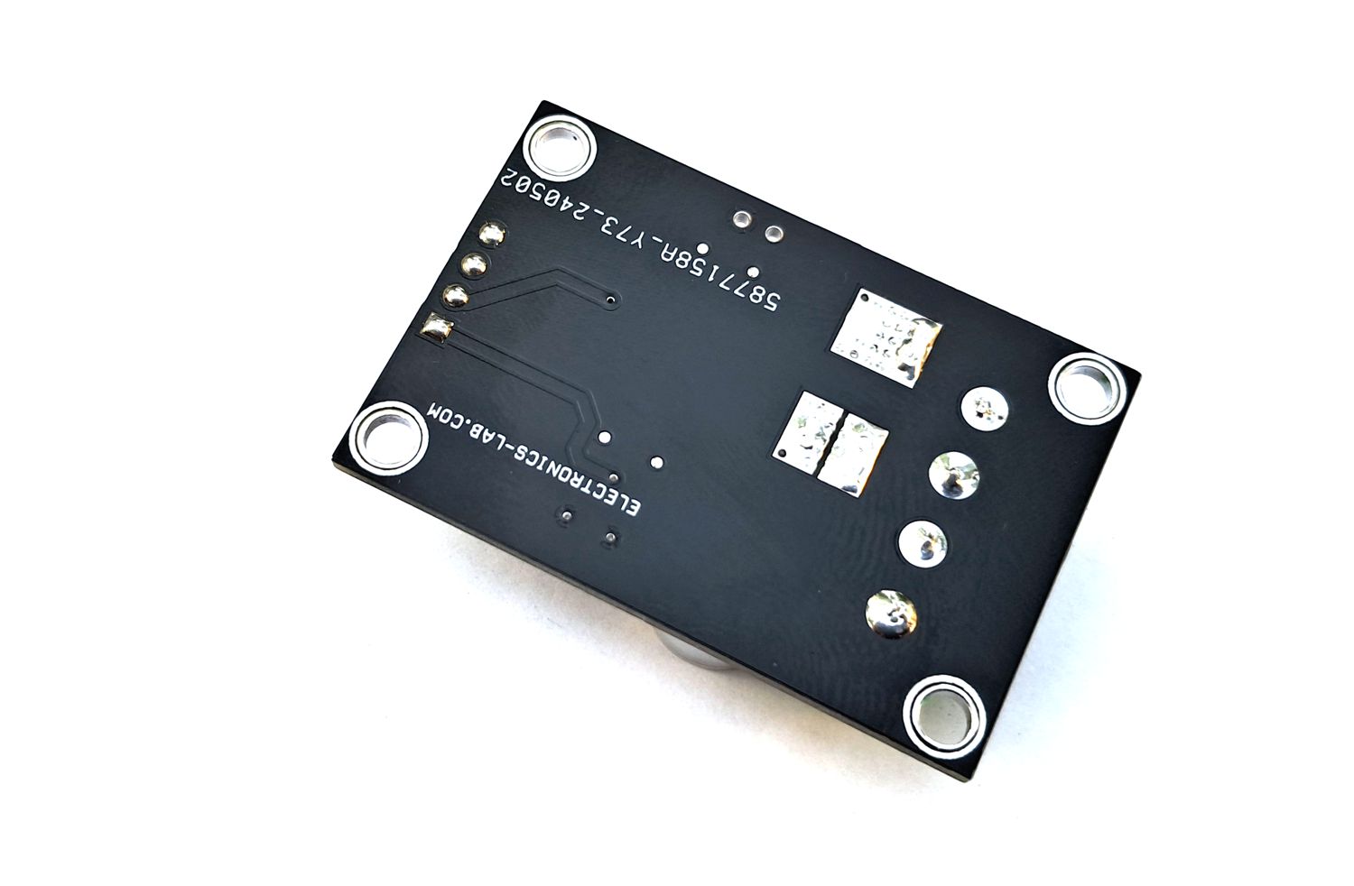
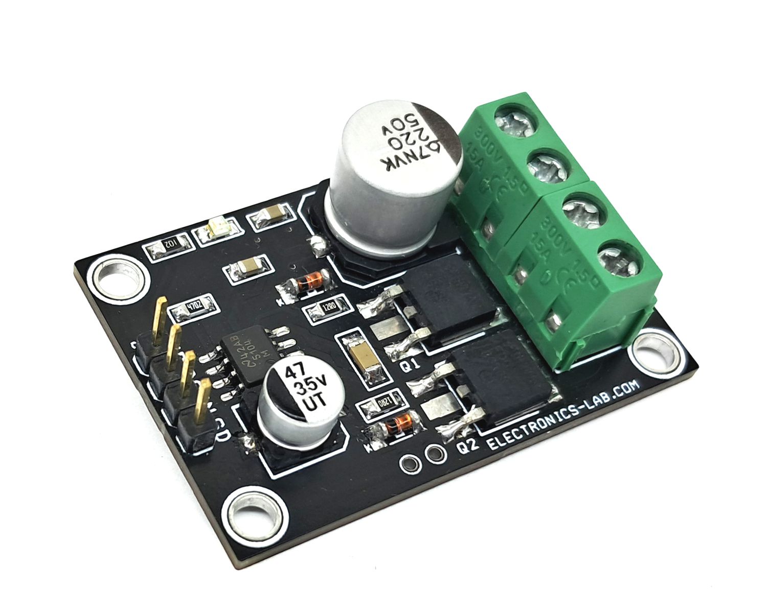
Photos
Video
LM5104 Datasheet
Please follow and like us:


PCB


Subscribe
Login
0 Comments