

Voltage Controlled Amplifier with Balanced Input
- Rajkumar Sharma
- 40 Views
- moderate
- Tested
- SKU: EL150155
- Quote Now
- 1 Likes

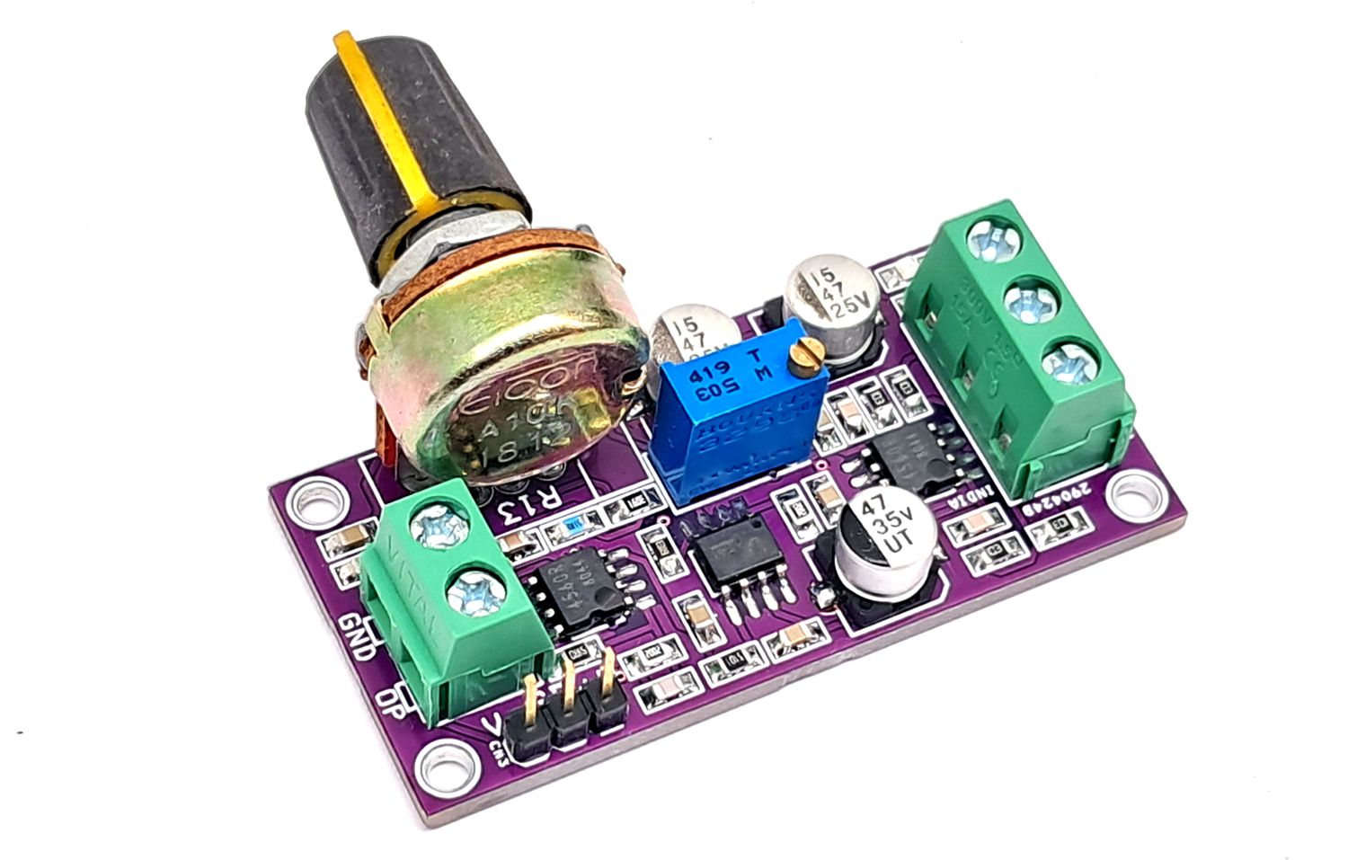
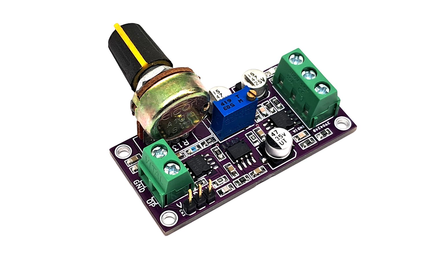
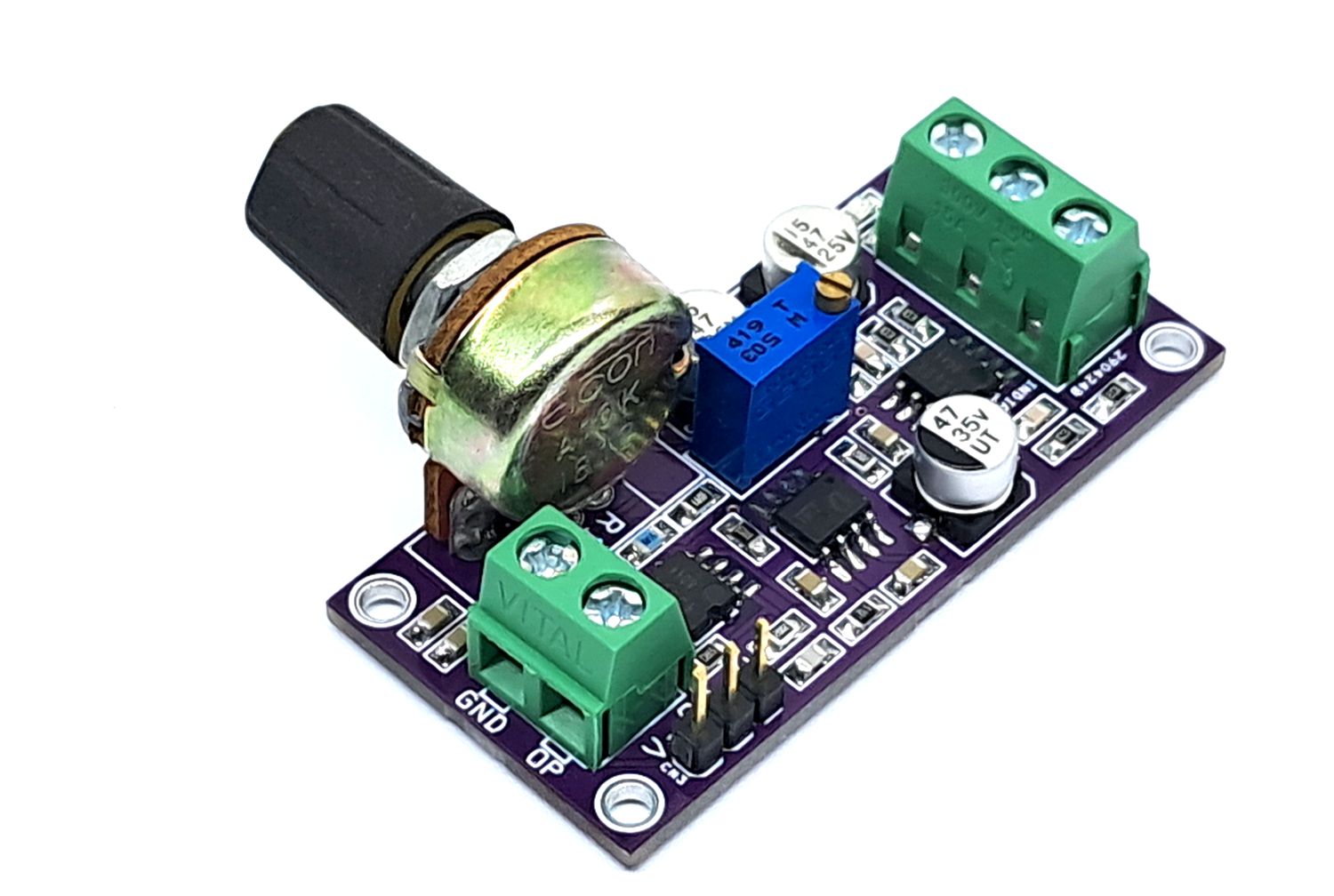
The project presented here is a Voltage Controlled Amplifier (VCA). A VCA board helps users control the audio level from a remote potentiometer. This board requires a balanced audio signal. Gain control voltage can be adjusted through potentiometer R13. The project works with a dual (±15V) power supply. Screw terminal connectors are provided for signal input and signal output. The project is built using THAT2181LA chip which is a VCA, designed for high performance in audio-frequency applications requiring exponential gain control, low distortion, wide dynamic range, and low control-voltage feedthrough. This chip controls the gain by converting an input current signal to a bipolar logged voltage, adding a DC control voltage, and re-converting the summed voltage back to a current through a bipolar antilog circuit. Stereo control of VCA with a single potentiometer is possible.
THAT2181–series trimmable Blackmer voltage-controlled amplifier (VCA) ICs are very high-performance current-in/current-out devices with two opposing-polarity, voltage-sensitive control ports. They offer wide-range exponential control of gain and attenuation with low signal distortion.
Trimming
The trim should be adjusted for minimum harmonic distortion using PR1. This is usually done by applying a middle-level, middle-frequency signal (e.g. 1 kHz at 1 V) to the audio input, setting the VCA to 0 dB gain, and adjusting the SYM trim while observing THD at the output. In 2181, this adjustment coincides closely with the setting which produces minimum control-voltage feedthrough, though the two settings are not always identical.
Features
- Power Supply +/-15V DC @ 40mA
- Total Harmonic Distortion 1V 0dB Gain 0.0025%
- Screw Terminal for Balanced Audio Input
- Header Connector for Power Input
- Screw Terminal for Audio Output
- On Board Power LED
- 5mm Mounting Holes
- PCB Dimensions 53.34 x 25.72mm
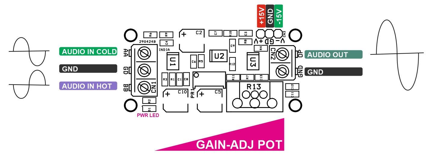
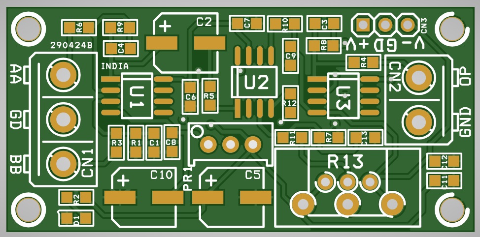
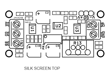
Connections
- CN1: Balance Audio Signal Input, Pin 1 = Audio-Hot, Pin 2 = GND, Pin 3 = Audio Cold
- CN2: Pin 1 = Audio Output, Pin 2 = GND
- CN3: Pin 1 = 15V DC, Pin 2 = GND, Pin 3 = -15V
- D1: Power LED
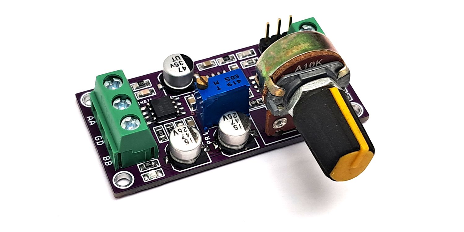
- R13: Gain Adjust Potentiometer
- PR1: Symmetry Adjust
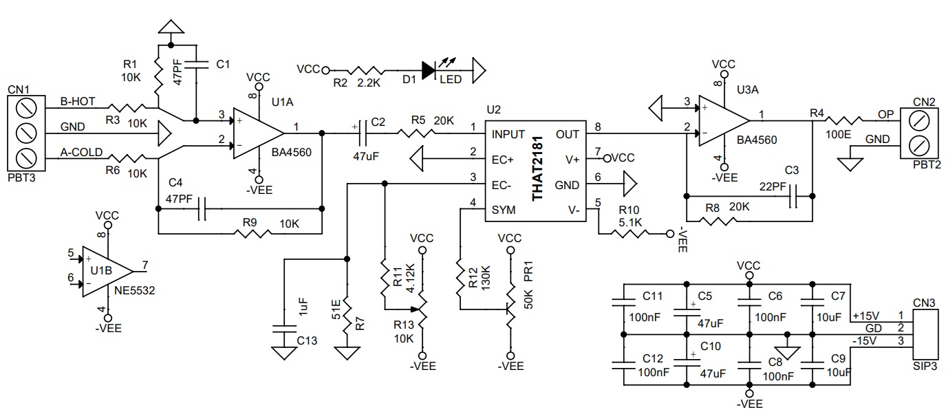
Schematic
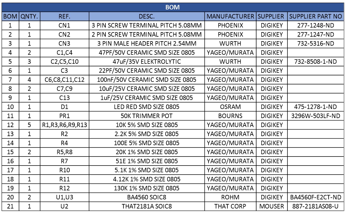
Parts List
| BOM | QNTY. | REF. | DESC. | MANUFACTURER | SUPPLIER | SUPPLIER PART NO |
|---|---|---|---|---|---|---|
| 1 | 1 | CN1 | 3 PIN SCREW TERMINAL PITCH 5.08MM | PHOENIX | DIGIKEY | 277-1248-ND |
| 2 | 1 | CN2 | 2 PIN SCREW TERMINAL PITCH 5.08MM | PHOENIX | DIGIKEY | 277-1247-ND |
| 3 | 1 | CN3 | 3 PIN MALE HEADER PITCH 2.54MM | WURTH | DIGIKEY | 732-5316-ND |
| 4 | 2 | C1,C4 | 47PF/50V CERAMIC SMD SIZE 0805 | YAGEO/MURATA | DIGIKEY | |
| 5 | 3 | C2,C5,C10 | 47uF/35V ELEKTROLYTIC | WURTH | DIGIKEY | 732-8508-1-ND |
| 6 | 1 | C3 | 22PF/50V CERAMIC SMD SIZE 0805 | YAGEO/MURATA | DIGIKEY | |
| 7 | 4 | C6,C8,C11,C12 | 100nF/50V CERAMIC SMD SIZE 0805 | YAGEO/MURATA | DIGIKEY | |
| 8 | 2 | C7,C9 | 10uF/25V CERAMIC SMD SIZE 0805 | YAGEO/MURATA | DIGIKEY | |
| 9 | 1 | C13 | 1uF/25V CERAMIC SMD SIZE 0805 | YAGEO/MURATA | DIGIKEY | |
| 10 | 1 | D1 | LED RED SMD SIZE 0805 | OSRAM | DIGIKEY | 475-1278-1-ND |
| 11 | 1 | PR1 | 50K TRIMMER POT | BOURNS | DIGIKEY | 3296W-503LF-ND |
| 12 | 5 | R1,R3,R6,R9,R13 | 10K 5% SMD SIZE 0805 | YAGEO/MURATA | DIGIKEY | |
| 13 | 1 | R2 | 2.2K 5% SMD SIZE 0805 | YAGEO/MURATA | DIGIKEY | |
| 14 | 1 | R4 | 100E 5% SMD SIZE 0805 | YAGEO/MURATA | DIGIKEY | |
| 15 | 2 | R5,R8 | 20K 1% SMD SIZE 0805 | YAGEO/MURATA | DIGIKEY | |
| 16 | 1 | R7 | 51E 1% SMD SIZE 0805 | YAGEO/MURATA | DIGIKEY | |
| 17 | 1 | R10 | 5.1K 1% SMD SIZE 0805 | YAGEO/MURATA | DIGIKEY | |
| 18 | 1 | R11 | 4.12K 1% SMD SIZE 0805 | YAGEO/MURATA | DIGIKEY | |
| 19 | 1 | R12 | 130K 1% SMD SIZE 0805 | YAGEO/MURATA | DIGIKEY | |
| 20 | 2 | U1,U3 | BA4560 SOIC8 | ROHM | DIGIKEY | BA4560F-E2CT-ND |
| 21 | 1 | U2 | THAT2181A SOIC8 | THAT CORP | MOUSER | 887-2181AS08-U |
Connections
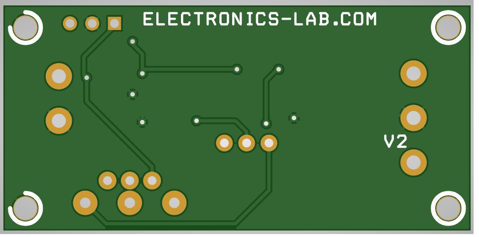
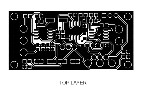
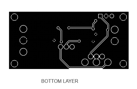
Gerber View
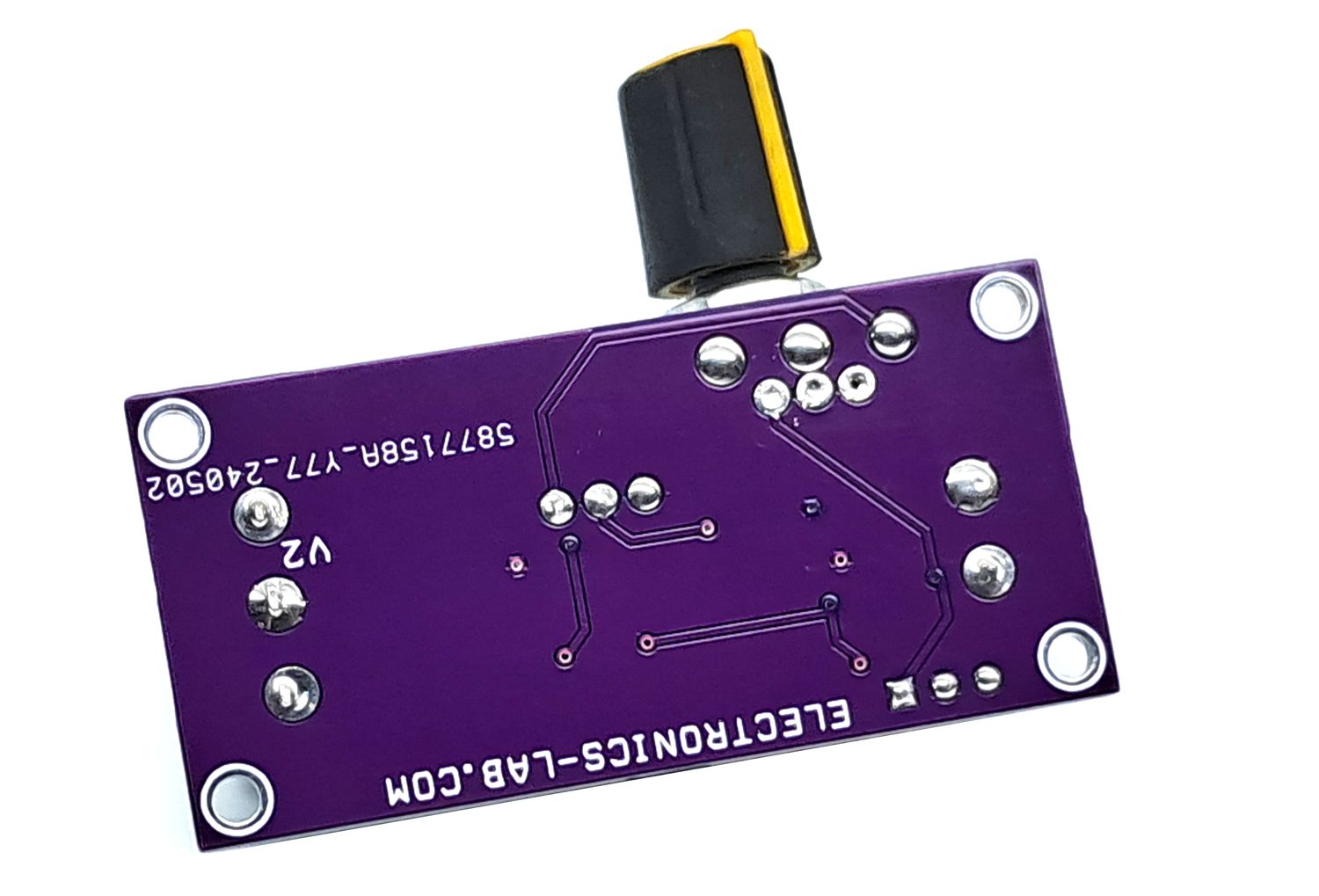
Photos
Video
THAT2181 Datasheet
Please follow and like us:


PCB


Subscribe
Login
0 Comments