

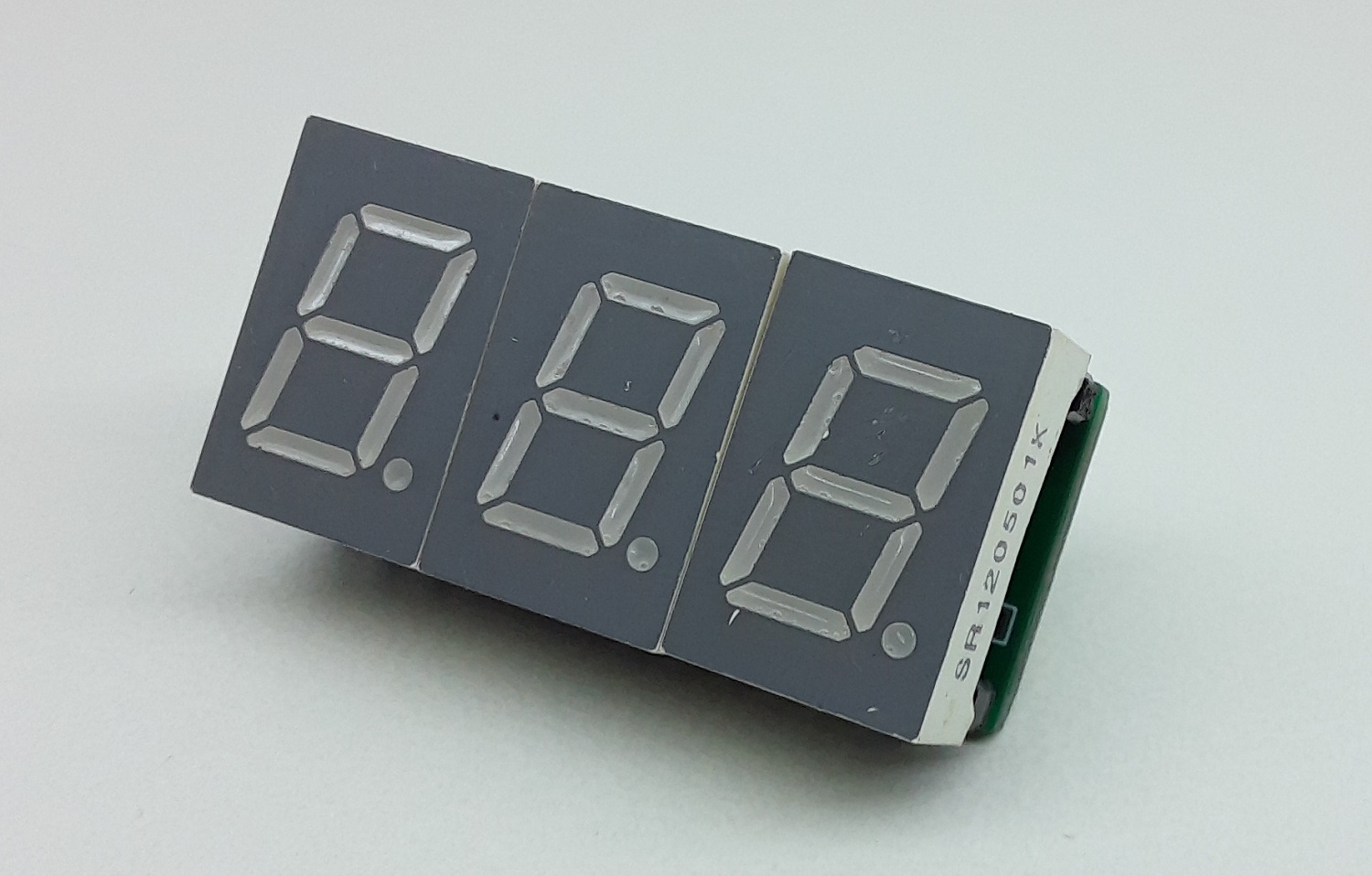
3 Digit Common Cathode 0.5″ – 7 Segment Display Module (Multiplexed)
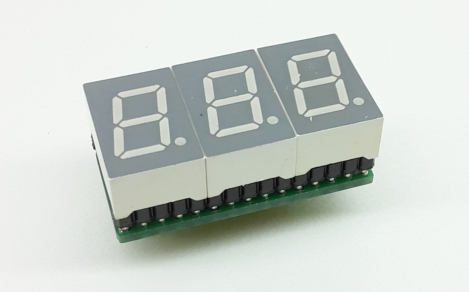
This is a 3 Digit 7-segment display project that contains 3 x Common Cathode displays, current limiting resistors or each LED segment, 3 x PNP Transistor on each common cathode for multiplexing etc. The project works with 5V TTL signals but can be optimized for 3.3V operations by reducing the current limiting resistors’ value. A header connector is provided for easy interface to Arduino or other microcontrollers. All inputs are TTL 5V compatible.
Multiplexed Display Info
https://en.wikipedia.org/wiki/Multiplexed_display
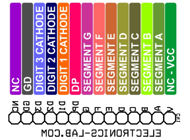
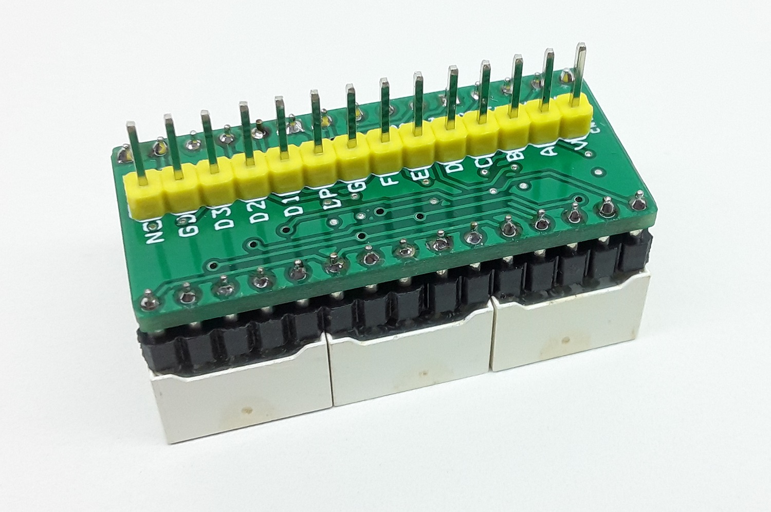
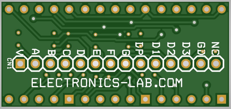
- PIN 1 NC (VCC-NO USE)
- PIN 2 SEGMENT A
- PIN 3 SEGMENT B
- PIN 4 SEGMENT C
- PIN 5 SEMENT D
- PIN 6 SEGMENT E
- PIN 7 SEGMENT F
- PIN 8 SEGMENT G
- PIN 9 DP
- PIN 10 DISPLAY 1 CATHODE (BC847 BASE)
- PIN 11 DISPLAY 2 CATHODE (BC847 BASE)
- PIN 12 DISPLAY 3 CATHODE (BC847 BASE)
- PIN 13 GND
- PIN 14 NC
Arduino Code
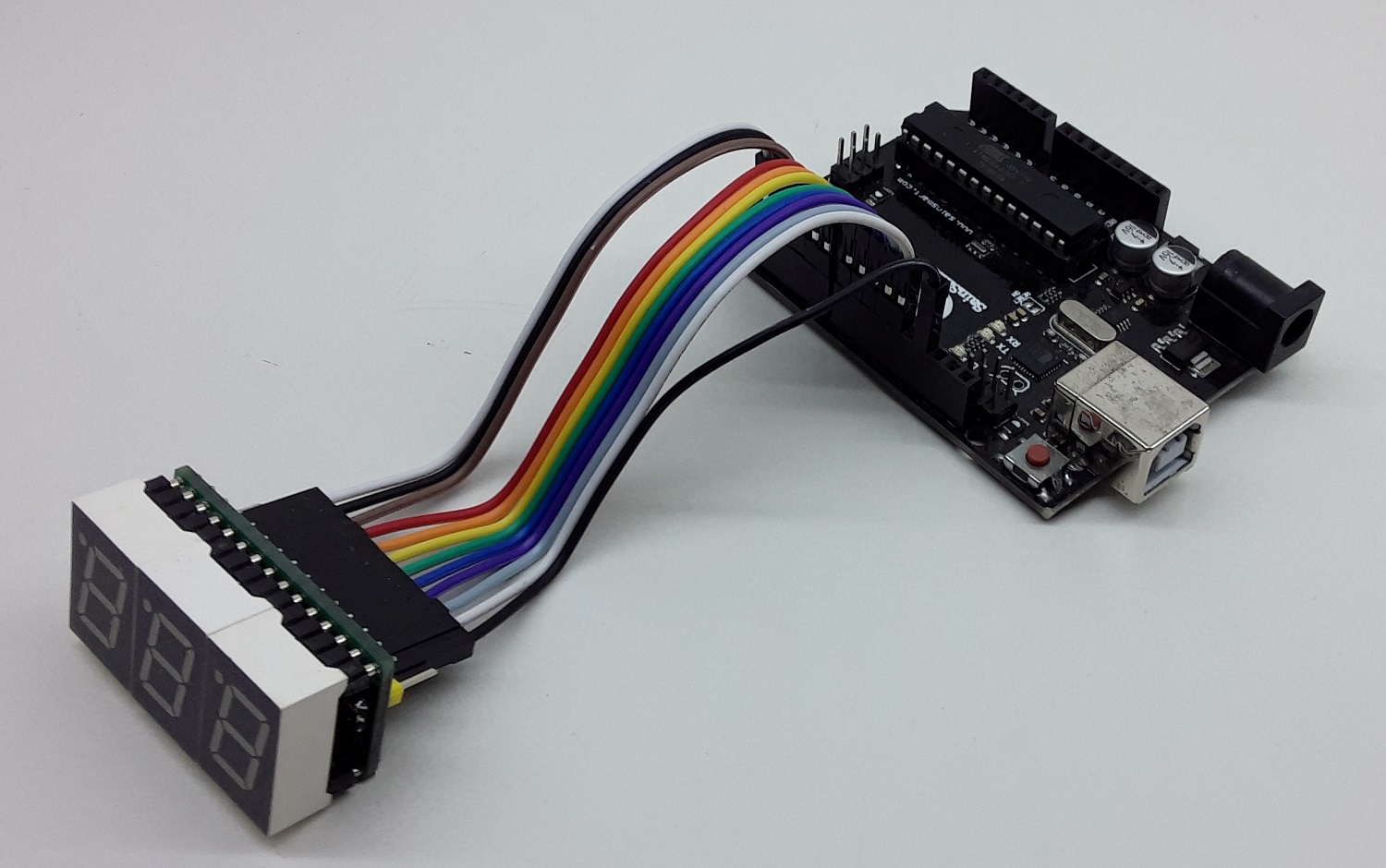
Arduino code is provided to test the board. The user will be able to create a 0 to 5V DC Voltmeter using this code. Upload the code to Arduino Uno, apply 0 to 5V to Analog Pin A0 to Measure the voltage. Refer Arduino pin configuration vs display bellow:
- Digital Pin D12 = Display 1 Cathode
- Digital Pin D11 = Display 2 Cathode
- Digital Pin D10 = Display 3 Cathode
- Digital Pin D2 = Display Segment A
- Digital Pin D3 = Display Segment B
- Digital Pin D4 = Display Segment C
- Digital Pin D5 = Display Segment D
- Digital Pin D6 = Display Segment E
- Digital Pin D7 = Display Segment F
- Digital Pin D8 = Display Segment G
- Digital Pin D9 = Display Segment DP
- Analog Pin Input = A0 5V Meter
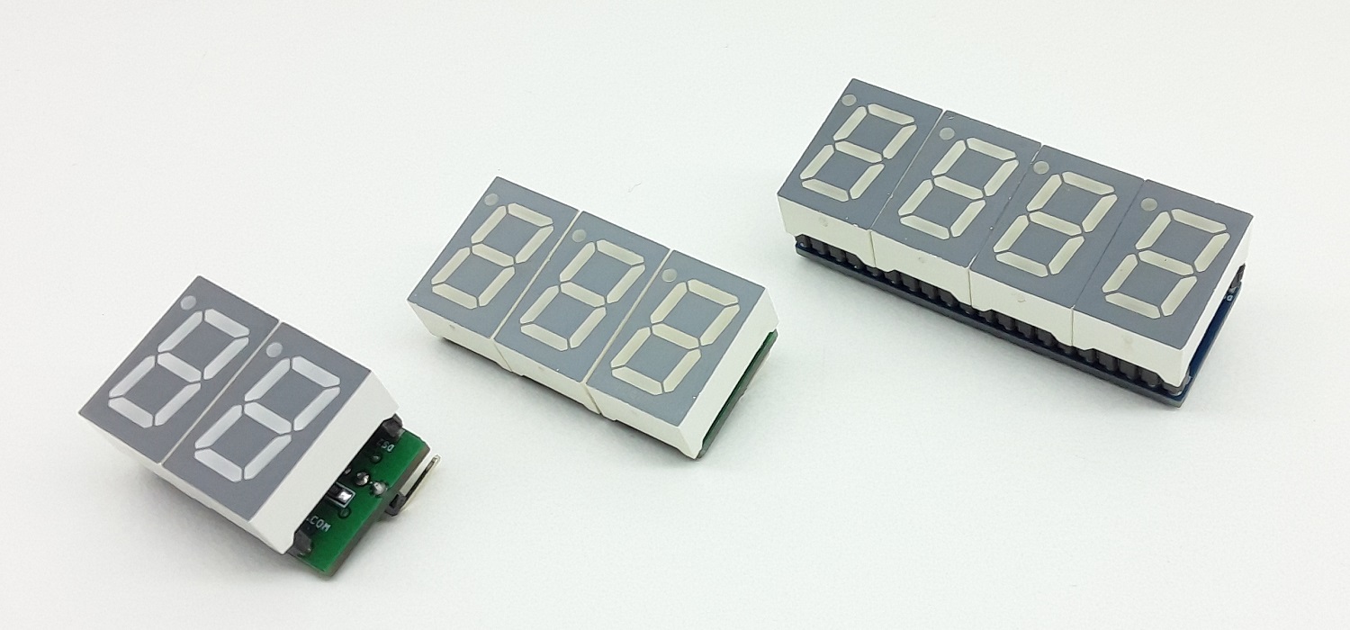
Similar modules
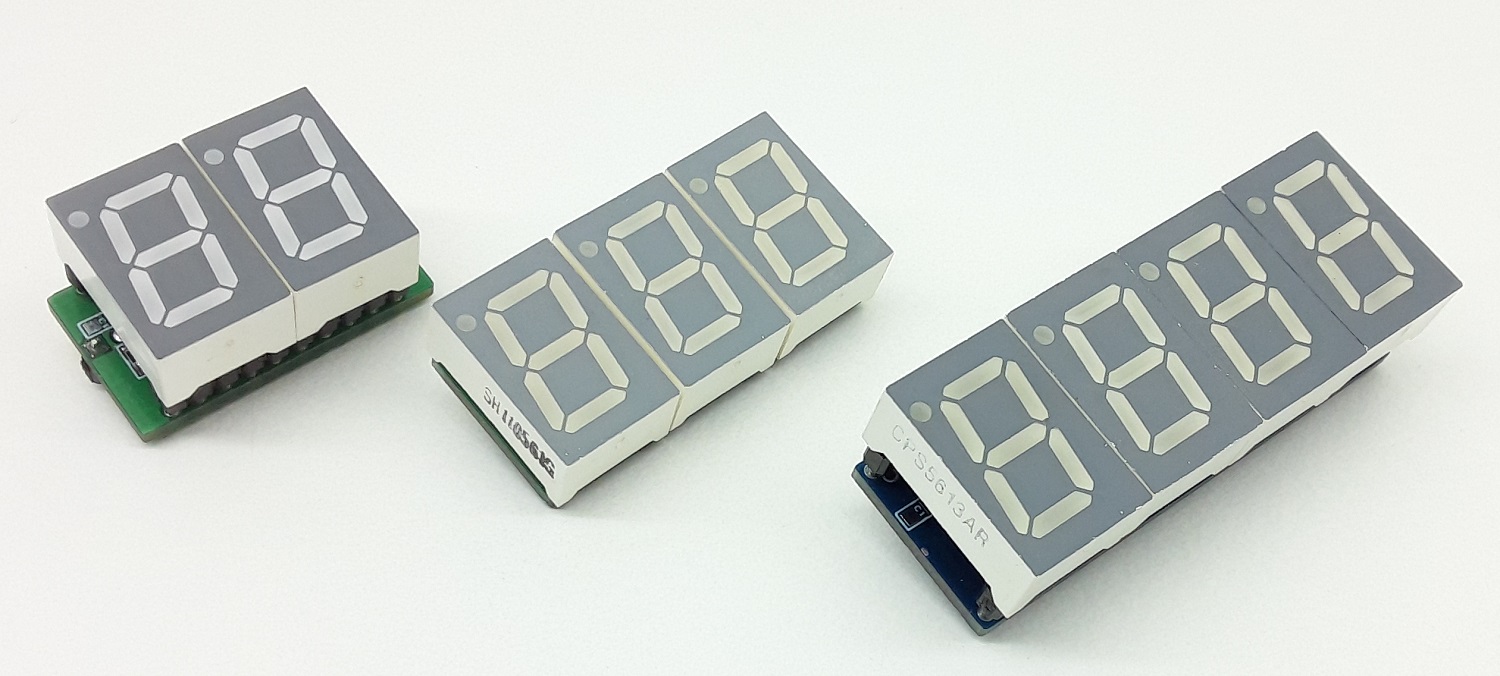
- 4 Digit Common Cathode 0.5″ – 7 Segment Display Module (Multiplexed)
- 2 Digit Common Cathode 0.5″ – 7 Segment Display Module (Multiplexed)
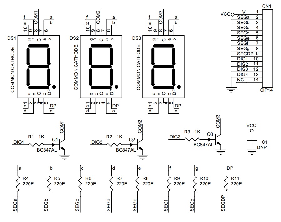
Schematic
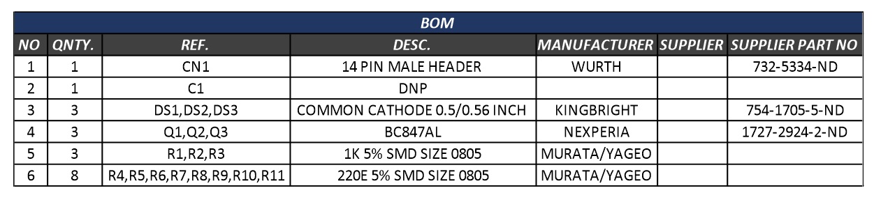
Parts List
| NO | QNTY. | REF. | DESC. | MANUFACTURER | SUPPLIER | PART NO |
|---|---|---|---|---|---|---|
| 1 | 1 | CN1 | 14 PIN MALE HEADER | WURTH | 732-5334-ND | |
| 2 | 1 | C1 | DNP | |||
| 3 | 3 | DS1,DS2,DS3 | COMMON CATHODE 0.5/0.56 INCH | KINGBRIGHT | 754-1705-5-ND | |
| 4 | 3 | Q1,Q2,Q3 | BC847AL | NEXPERIA | 1727-2924-2-ND | |
| 5 | 3 | R1,R2,R3 | 1K 5% SMD SIZE 0805 | MURATA/YAGEO | ||
| 6 | 8 | R4,R5,R6,R7,R8,R9,R10,R11 | 220E 5% SMD SIZE 0805 | MURATA/YAGEO |
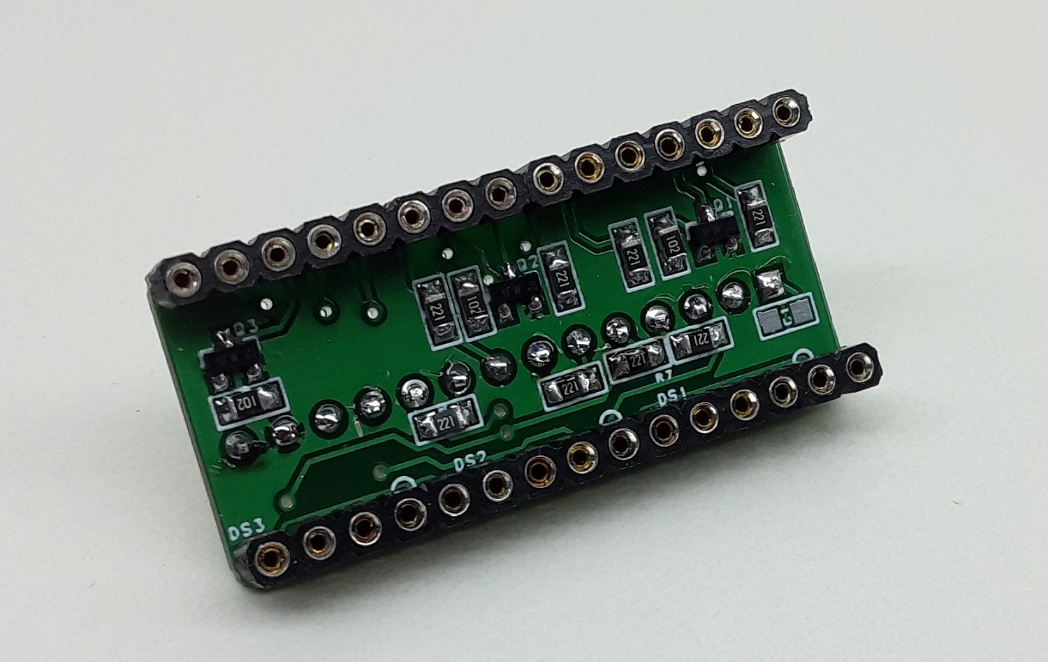
Connections
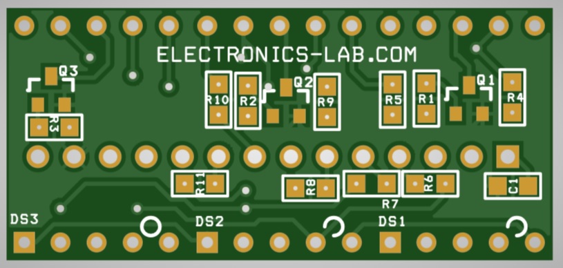
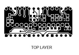
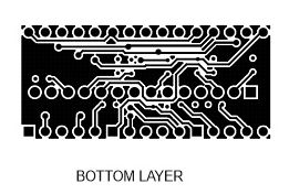
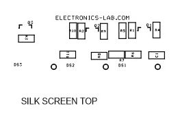
Gerber View
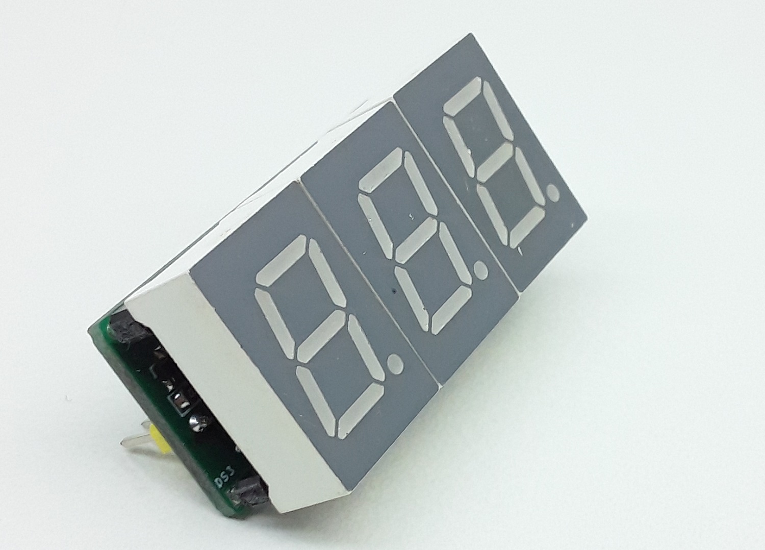
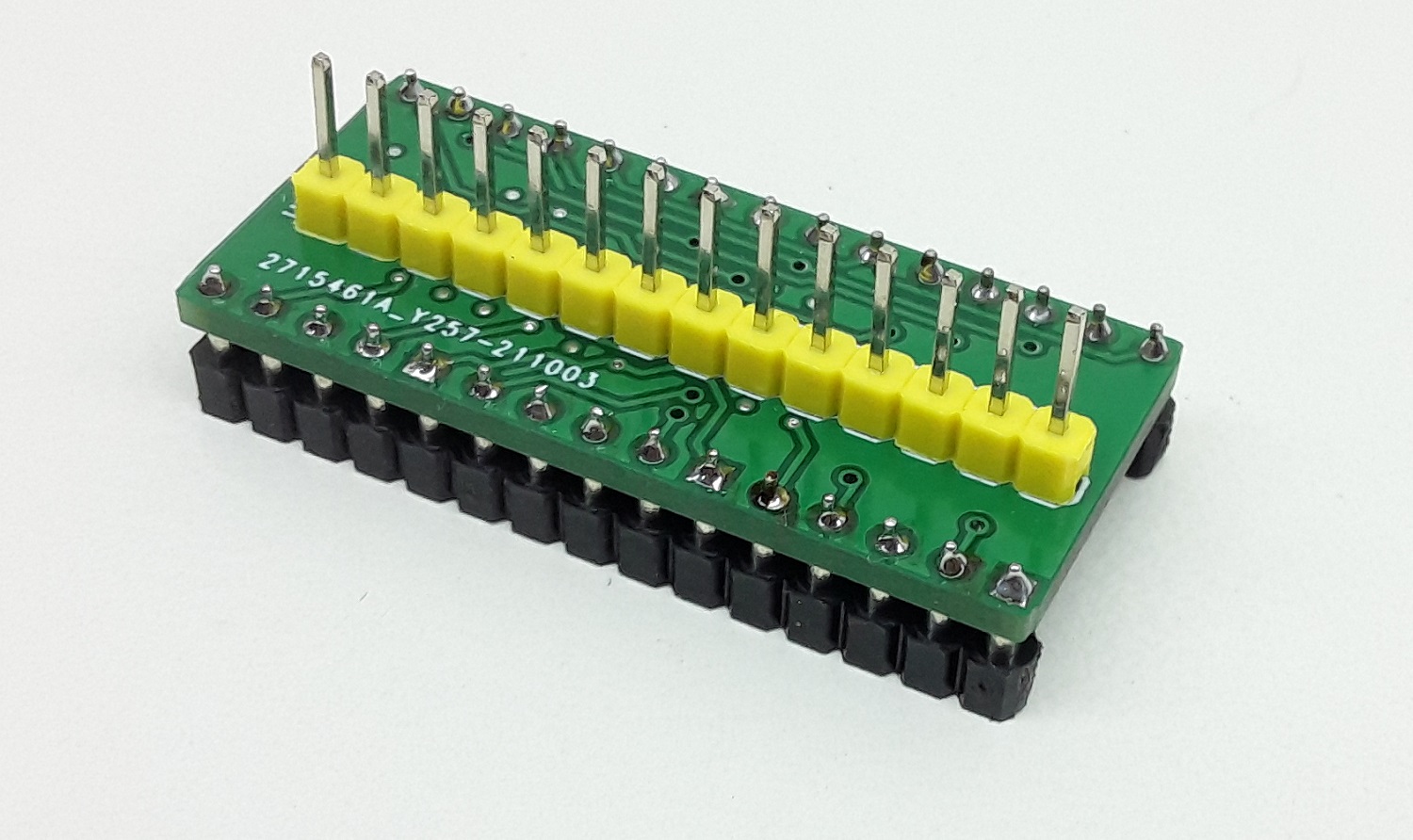
Photos
Video
SC56-21SRWA Datasheet
Please follow and like us:
PCB


Subscribe
Login
0 Comments


")
")
