3 Phase Brushless Motor Driver using L6235
- Rajkumar Sharma
- 202 Views
- moderate
- Tested
- SKU: EL140772
- Quote Now
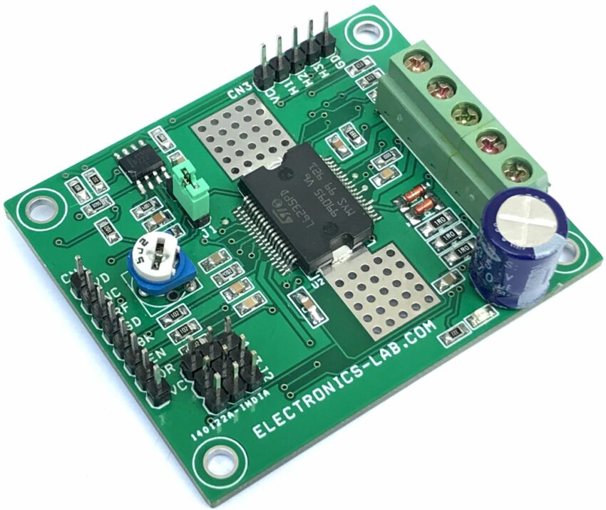
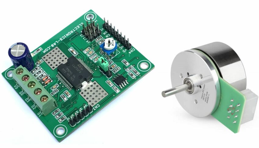
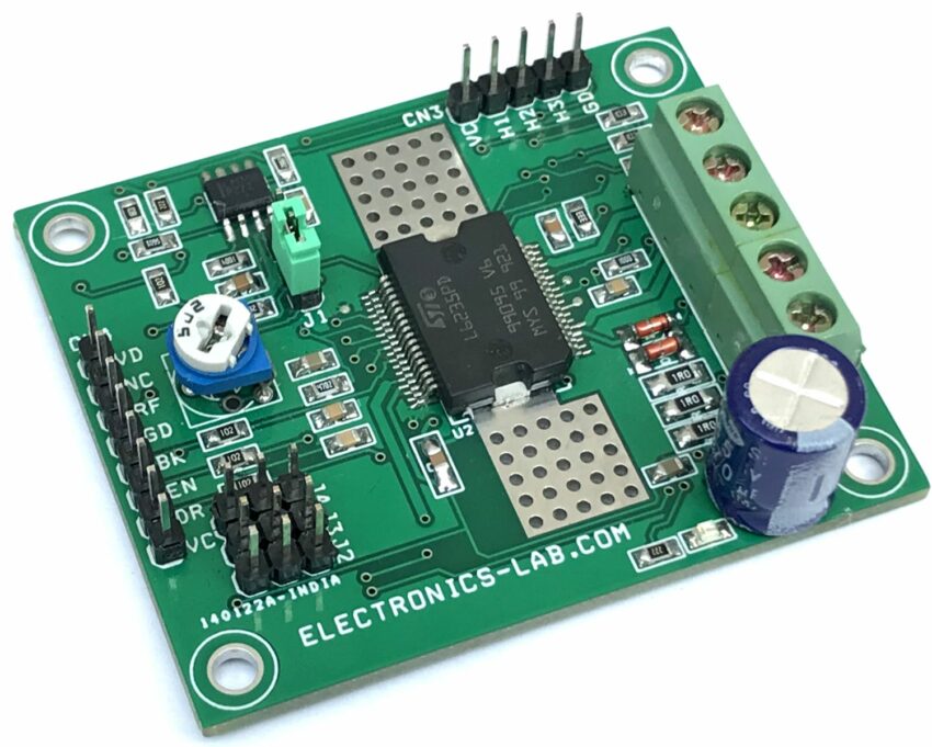
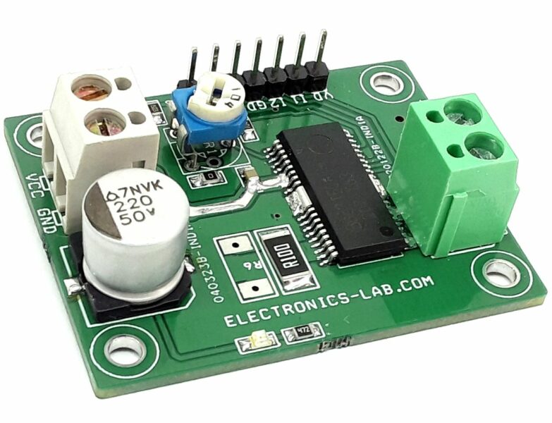
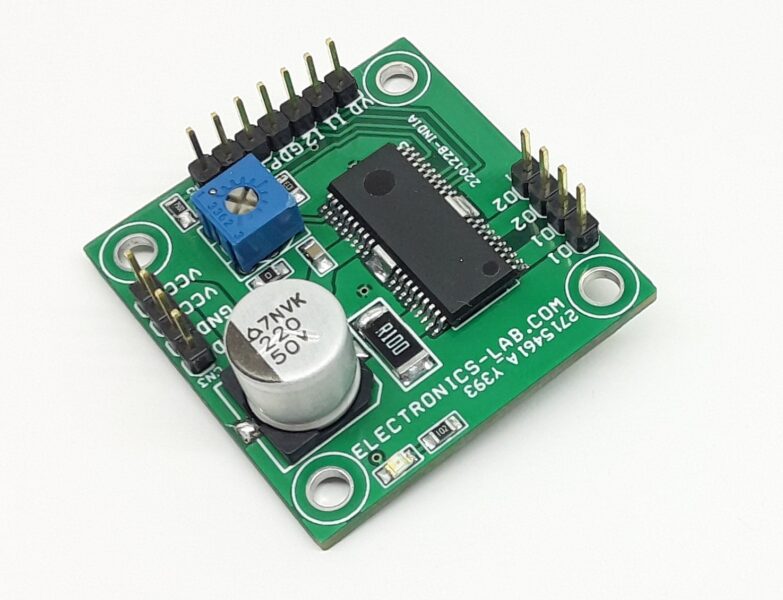
The project presented here is a 3-phase Brushless motor driver. The project consists of an L6235 device which is DMOS fully integrated 3-phase motor driver with overcurrent protection. Manufactured in BCD technology, the device combines isolated DMOS power transistors with CMOS and bipolar circuits on the same chip. The device includes all the circuitry needed to drive a 3-phase BLDC motor including a 3-phase DMOS bridge, a constant off-time PWM current controller, and the decoding logic for single-ended hall sensors that generates the required sequence for the power stage. Running the project in stand-alone mode, instead, three control pins enable the device, setting the direction of the rotation, breaking the motor, and the jumper chooses to run in torque or speed mode. The board is suitable for small motors used in many home appliances and can handle torque and speed control with a high efficiency of up to 95%.
Operation
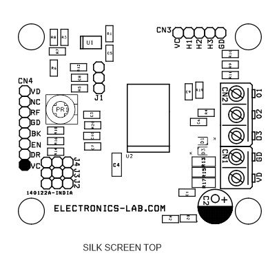
- CN4: Pin2 High/Low to select the Direction of the Motor
- CN4: Pin 3 Enable, High=Enable, Low = Disable
- CN4: Pin 4 Brake, High=Normal Operation, Low=Brake
- J1: Jumper Speed Mode or Torque Mode Selection
- PR1: Adjust the Speed
Features
- Operating supply voltage from 8 to 48 V
- Load Current Up to 2.8A, Peak Current 5.6Amp
- Non-dissipative overcurrent detection and protection
- Diagnostic output
- Constant tOFF PWM current controller
- Slow decay synchr. rectification
- 60° and 120° hall effect decoding logic
- Brake function
- Cross conduction protection
- Thermal shutdown
- Undervoltage lockout
- Integrated fast freewheeling diodes (Chip)
- 4 x 3mm Mounting Holes
- PCB Dimensions 59.69 x 49.53mm
Current Ratings
Load current rated for a maximum of 2.8ARMS. and 5.6Apeak. The device has a built-in Over-Current Detection (OCD) that allows protection against short circuits between the outputs and between the output and ground.
Voltage Ratings and Operation Range
The L6235 requires a single supply voltage (VS), for the motor supply. The operating range for VS is 8 to 48 V. To prevent working into undesirable low supply voltage an Under Voltage Lock Out (UVLO) circuit shuts down the device when the supply voltage falls below 6 V; to resume normal operating conditions, VS must then exceed 7 V. The hysteresis is provided to avoid false intervention of the UVLO function during fast VS ringing’s. It should be noted, however, that DMOS’s RDS(ON) is a function of the VS supply voltage. Actually, when VS is less than 10V, RDS(ON) is adversely affected, and this is particularly true for the High Side DMOS that are driven from VBOOT supply. This supply is obtained through a charge pump from the internal 10V supply, which will tend to reduce its output voltage when VS goes below 10V.
Brake
In general, motor braking can be achieved by making a short circuit across the windings: the BEMF forces a current, proportional to the braking torque, that flows in the opposite direction than in normal running mode. For high BEMF and inertia moment, the current may reach very high values: a power resistor is often used to reduce the maximum braking current and dissipate the motor energy. L6235 Brake pin can be used to quickly stop the motor while it is running: providing a low logic level to this pin all the high-side DMOS switch on, making a short-circuit across the motor windings. A power resistor is not used: while the motor is braking, both Thermal and Over-Current protections still work, avoiding BEMF from causing a current exceeding the device’s maximum ratings.
Connections and Other Details
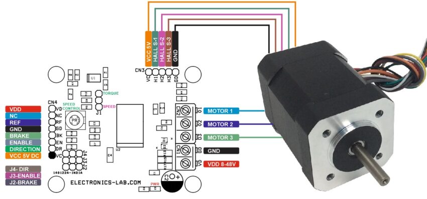
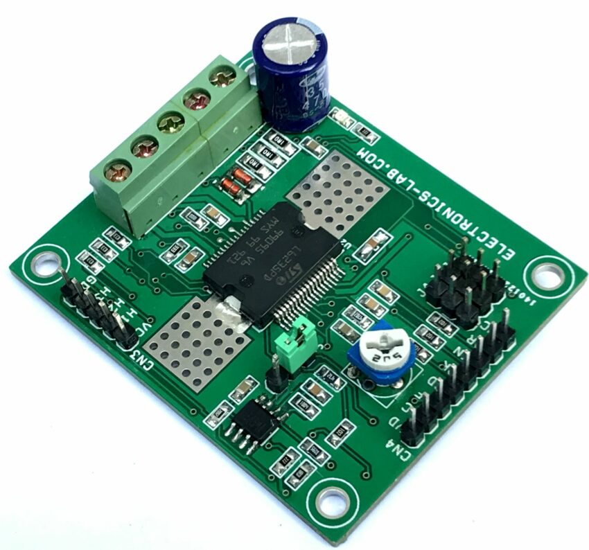
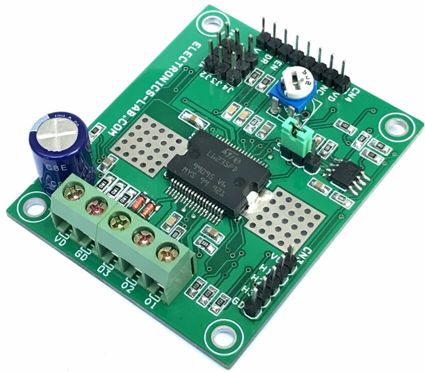
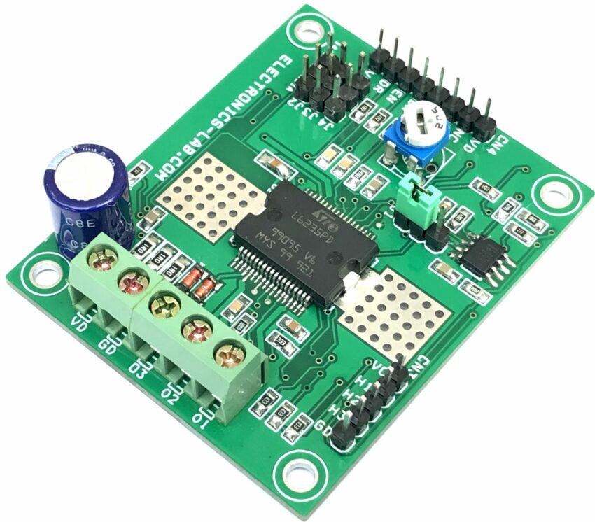
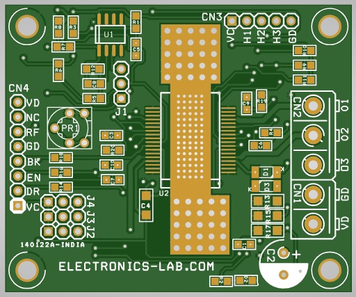
- CN1: Pin 1 = VDD 8 to 48V DC Motor Power, Pin 2 = GND
- CN2: Pin 1 = Motor 1, Pin 2 = Motor 2, Pin 3 = Motor 3
- CN3: Pin 1 VCC 5V DC, Pin 2 = Hall Sensor 1, Pin 3 = Hall Sensor 2, Pin 4 = Hall Sensor 3
- CN4: Pin 1 = VCC, Pin 2 = Direction, Pin 3 = Enable, Pin 4 = Brake, Pin 5 = GND, Pin 6 = Ref No Use, Pin 7 = NC, Pin 8 = VDD 8 to 48V
- PR1: Speed Control
- J1: Jumper for Speed Control or Torque Control Selection
- J2: Jumper for Brake
- J3: Jumper for Enable
- J4: Jumper for Direction
- D2: Motor Power LED
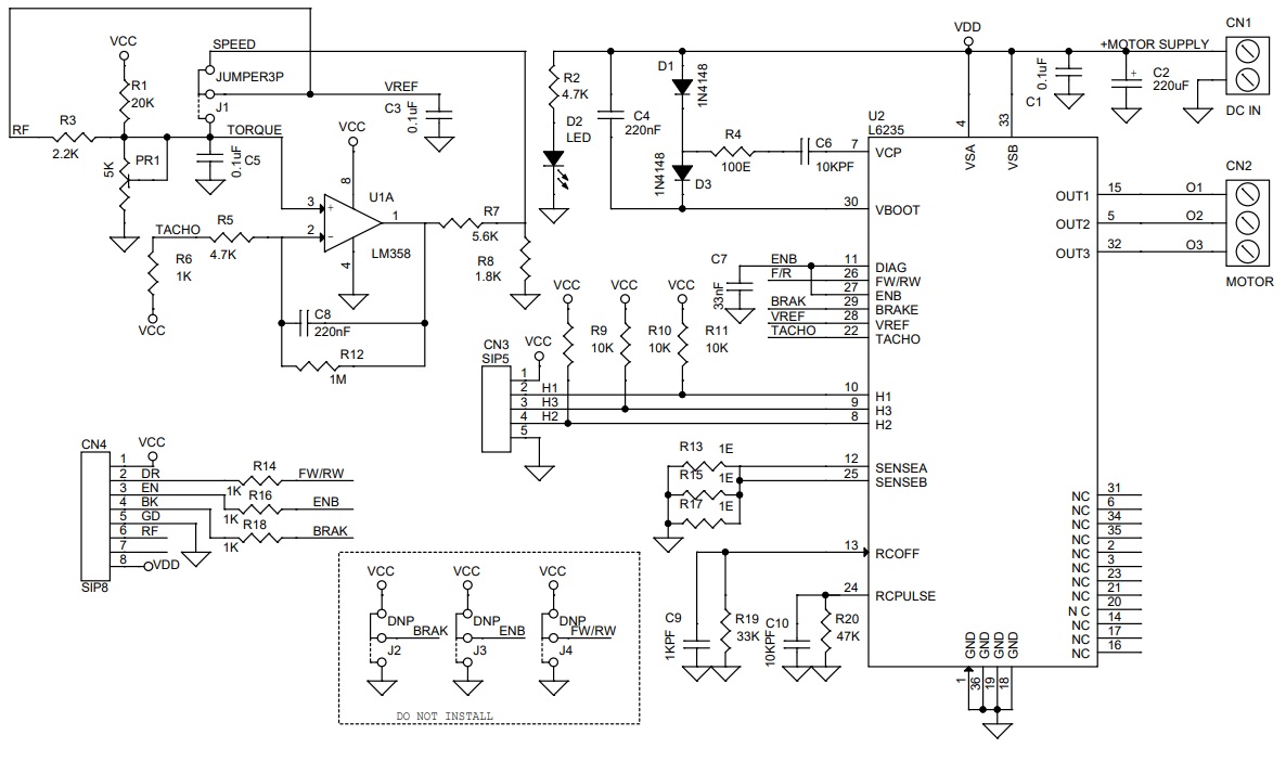
Schematic
Parts List
| NO. | QNTY. | REF. | DESC. | MANUFACTURER | SUPPLIER | SUPPLIER PART NO |
|---|---|---|---|---|---|---|
| 1 | 1 | CN1 | 2 PIN SCREW TERMINAL PITCH 5.08MM | PHOENIX | DIGIKEY | 277-1247-ND |
| 2 | 1 | CN2 | 3 PIN SCREW TERMINAL PITCH 5.08MM | PHOENIX | DIGIKEY | 277-1248-ND |
| 3 | 1 | CN3 | 5 PIN MALE HEADER PITCH 2.54MM | WURTH | DIGIKEY | 732-5318-ND |
| 4 | 1 | CN4 | 8 PIN MALE HEADER PITCH 2.54MM | WURTH | DIGIKEY | 732-5321-ND |
| 5 | 3 | C1,C3,C5 | 0.1uF/50V CERAMIC SMD SIZE 0805 | YAGEO/MURATA | DIGIKEY | |
| 6 | 1 | C2 | 220uF/50V ELECTROLYTIC THT | PANASONIC | DIGIKEY | P10398TB-ND |
| 7 | 2 | C8 | 220nF/50V CERAMIC SMD SIZE 0805 | YAGEO/MURATA | DIGIKEY | |
| 8 | 2 | C6,C10 | 10KPF/50V CERAMIC SMD SIZE 0805 | YAGEO/MURATA | DIGIKEY | |
| 9 | 1 | C7 | 33nF/50V CERAMIC SMD SIZE 0805 | YAGEO/MURATA | DIGIKEY | |
| 10 | 1 | C9 | 1KPF/50V CERAMIC SMD SIZE 0805 | YAGEO/MURATA | DIGIKEY | |
| 11 | 2 | D1,D3 | 1N4148 | MICROCHIP | DIGIKEY | 1N4148UR-1-ND |
| 12 | 1 | D2 | LED RED SMD SIZE 0805 | OSRAM | DIGIKEY | 475-1278-1-ND |
| 13 | 1 | C4 | 220nF/50V CERAMIC SMD SIZE 1206 | YAGEO/MURATA | DIGIKEY | |
| 14 | 4 | J1,J2,J3,J4 | 3 PIN MALE HEADER PITCH 2.54MM | WURTH | DIGIKEY | 732-5316-ND |
| 15 | 1 | PR1 | 5K TRIMMER POTENTIOMETER | BOURNS | DIGIKEY | 3362P-502LF-ND |
| 16 | 1 | R1 | 20K 1% SMD SIZE 0805 | YAGEO/MURATA | DIGIKEY | |
| 17 | 2 | R2,R5 | 4.7K 5% SMD SIZE 0805 | YAGEO/MURATA | DIGIKEY | |
| 18 | 1 | R3 | 2.2K 5% SMD SIZE 0805 | YAGEO/MURATA | DIGIKEY | |
| 19 | 1 | R4 | 100E 5% SMD SIZE 0805 | YAGEO/MURATA | DIGIKEY | |
| 20 | 4 | R6,R14,R16,R18 | 1K 5% SMD SIZE 0805 | YAGEO/MURATA | DIGIKEY | |
| 21 | 1 | R7 | 5.6K 5% SMD SIZE 0805 | YAGEO/MURATA | DIGIKEY | |
| 22 | 1 | R8 | 1.8K 5% SMD SIZE 0805 | YAGEO/MURATA | DIGIKEY | |
| 23 | 3 | R9,R10,R11 | 10K 5% SMD SIZE 0805 | YAGEO/MURATA | DIGIKEY | |
| 24 | 1 | R12 | 1M 5% SMD SIZE 0805 | YAGEO/MURATA | DIGIKEY | |
| 25 | 3 | R13,R15,R17 | 1E 1% SMD SIZE 1206 | YAGEO/MURATA | DIGIKEY | |
| 26 | 1 | R19 | 33K 5% SMD SIZE 0805 | YAGEO/MURATA | DIGIKEY | |
| 27 | 1 | R20 | 47K 5% SMD SIZE 0805 | YAGEO/MURATA | DIGIKEY | |
| 28 | 1 | U1 | LM358 SOIC8 | TI | DIGIKEY | 296-14601-1-ND |
| 29 | 1 | U2 | L6235 | ST | DIGIKEY | 497-4010-1-ND |
| 30 | 4 | SHUNT | SHUNT FOR JUMPERS | SULLINS CONECT | DIGIKEY | S9001-ND |
Connections


