

Mini Robot Controller Using Infra-Red Remote for Small and Medium Size Robot
- Rajkumar Sharma
- 305 Views
- easy
- Tested
- SKU: EL129580
- Quote Now
- 0 Likes

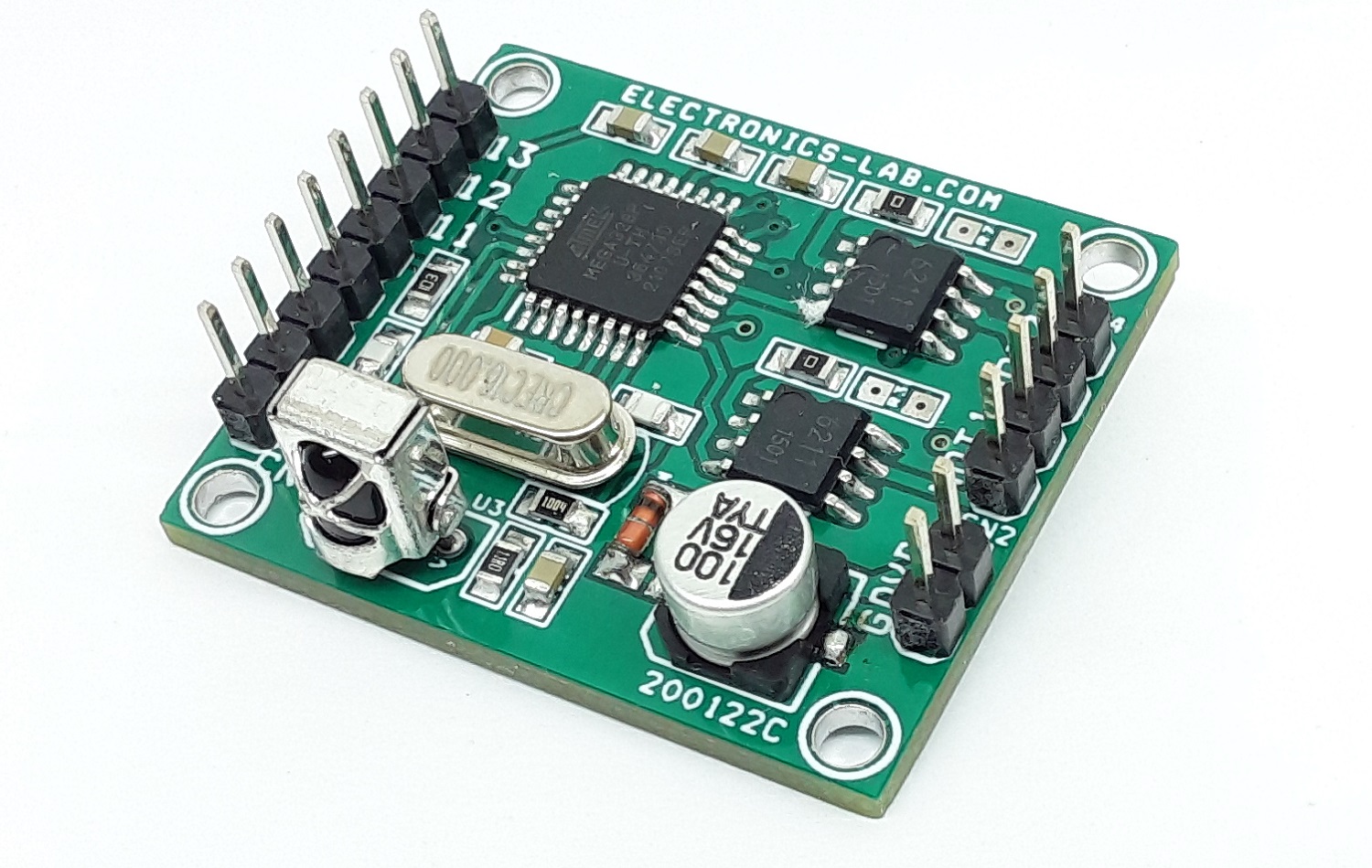
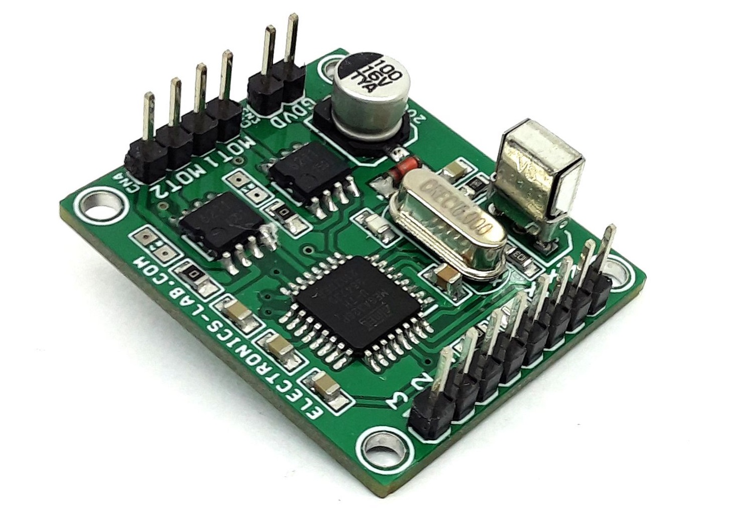
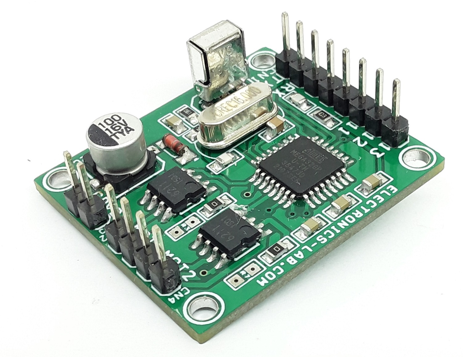
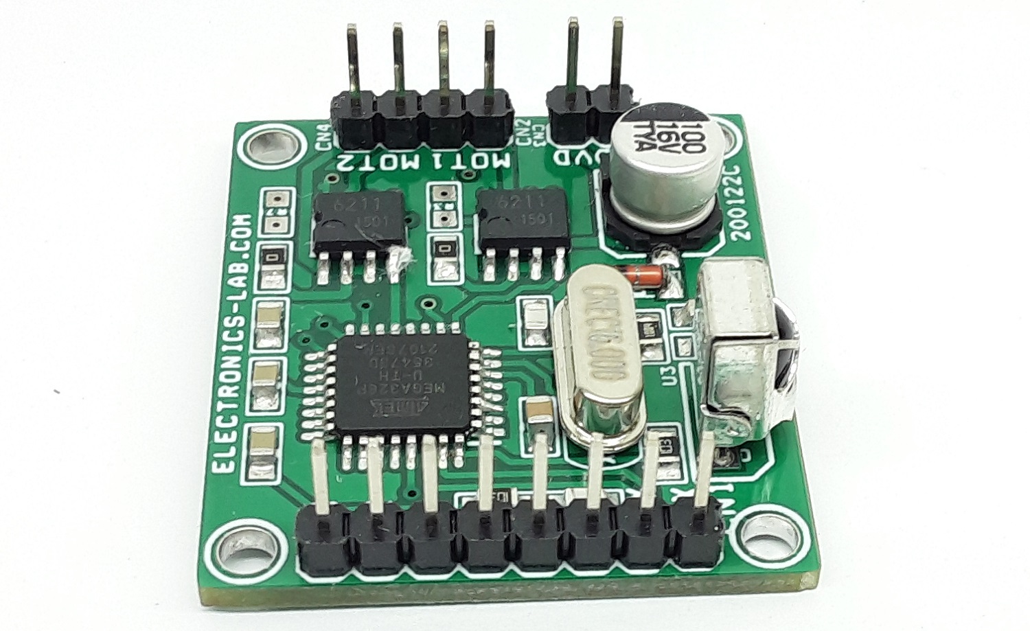
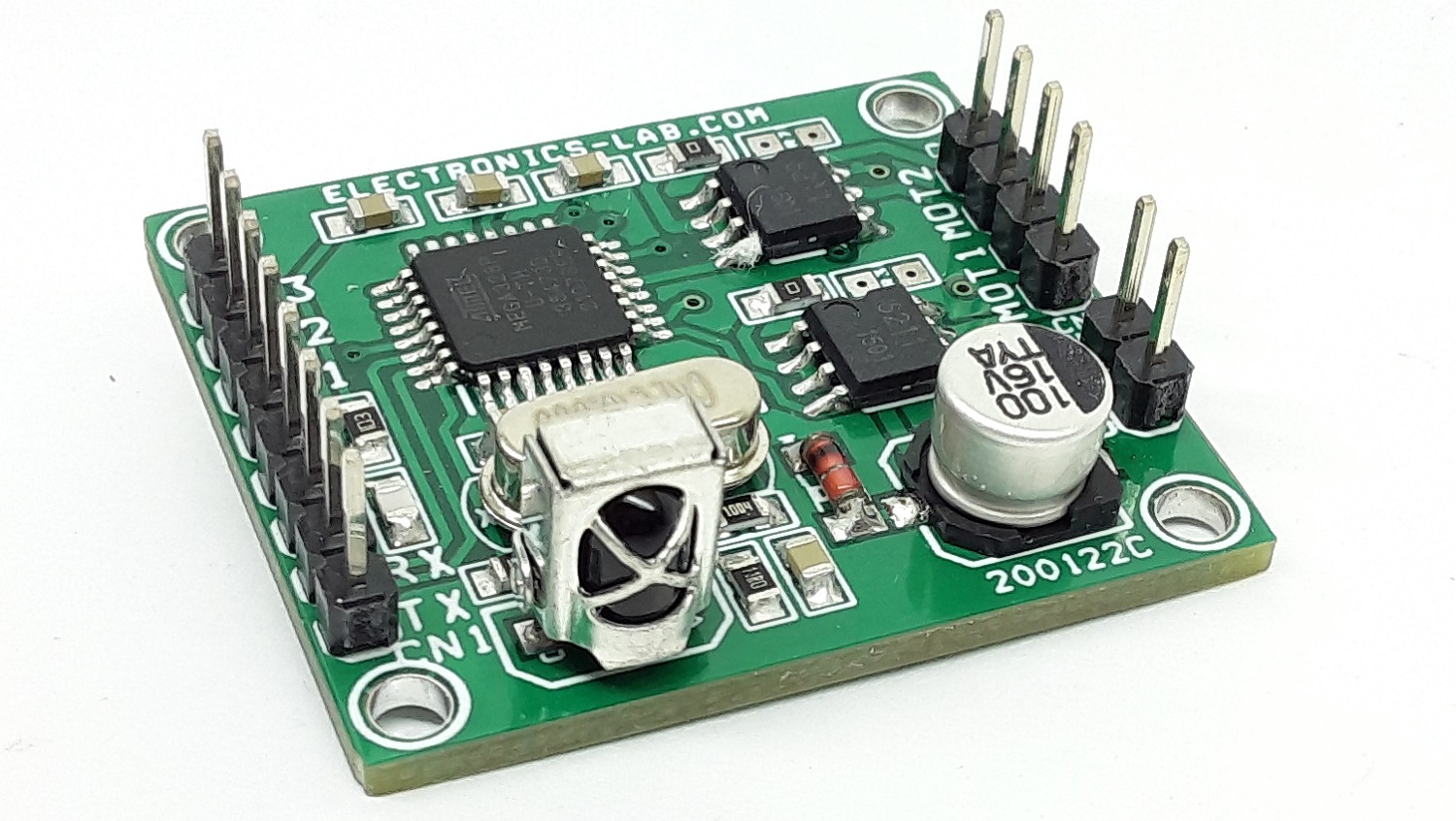
The Robot Controller is a very compact solution for controlling small and medium size robots using an Infrared remote. The project is fully Arduino compatible and consists of an ATMEGA328 microcontroller, 2 x BD6211 motor drivers, TSOP1838 IR sensor. BD6211 H-bridge is a full bridge driver for brush motor. The reference pin of BD6211 is pulled high and needs 2 x input to control the direction of the motor. 2 input pins of BD6211 are connected to ATMEGA328 for direction control of the motor. The project can be used to drive dual motors for 3-wheel robots or 4 x mini-DC motors. Input power supply 4.5V to 5.5V DC, the project can drive load up to 1A for each channel. Connector CN1 is provided to program the ATMEGA328 chips using Arduino IDE.
Arduino Code 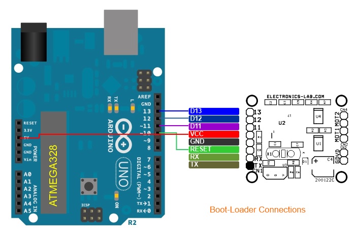
Arduino example code is available as a download to test the board. With this code user will be able to drive 3-wheel robot with 2 Motors, and 5 functions Forward, Reverse, Turn Left, Turn Right, and Stop
Follow bellow link to learn more about programming and boot-loader burning for a new ATMEGA328 chip.
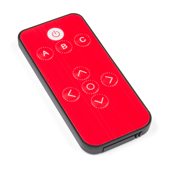
The project tested using Spark fun IR Mini Remote (COM-14865)
Recommended to include the IR Remote library before programming the board.
Remote Operations: 5 Switches used for full operations, 4 Directions, and Select Switch
- Forward, Reverse, Turn Left, Turn Right, Stop
Arduino Pins
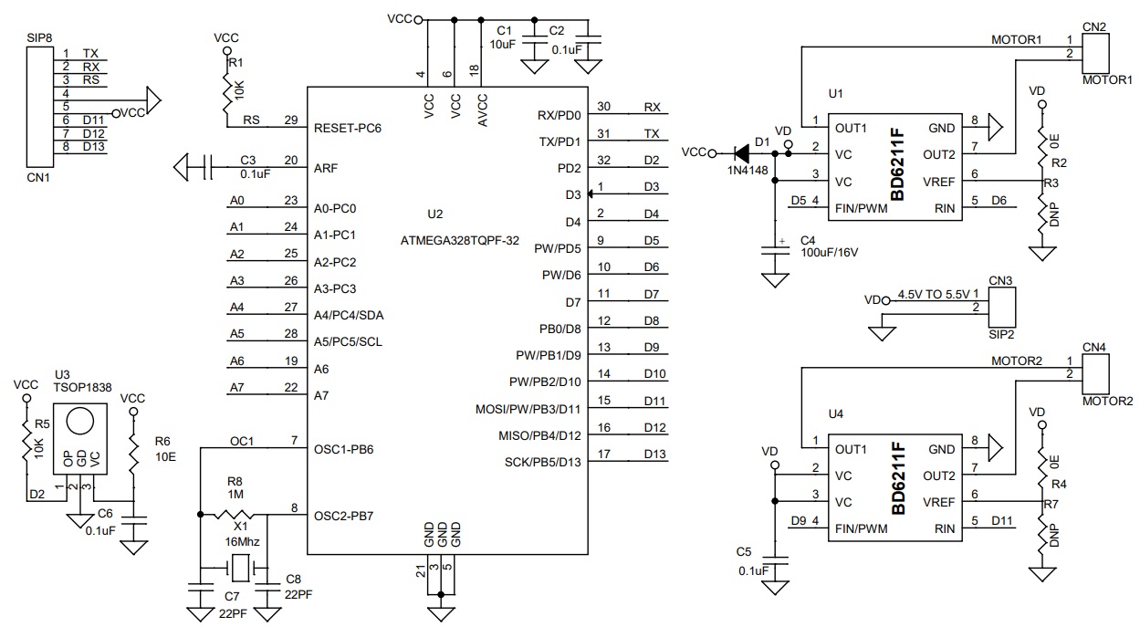
- Digital Pin D5 Motor-1 Driver BD6211 FIN
- Digital Pin D6 Motor-1 Driver BD6211 RIN
- Digital Pin D9 Motor-2 Driver BD6211 FIN
- Digital Pin D11 Motor-2 Driver BD6211 RIN
- Digital Pin D2 Infra-Red Sensor
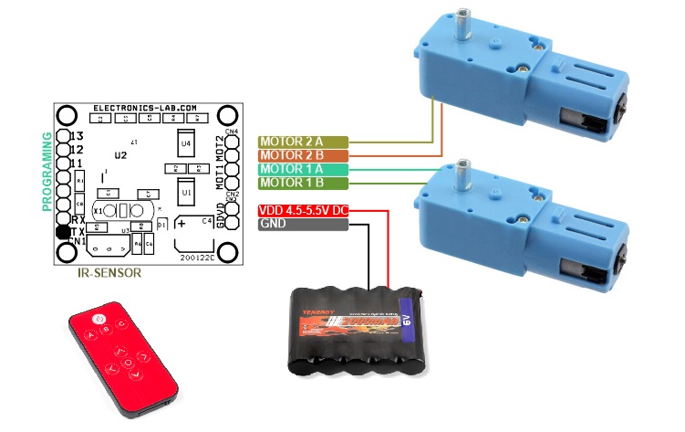
Connections
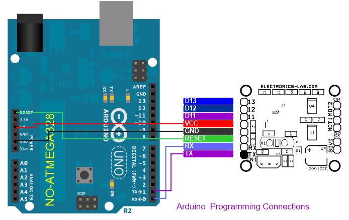
- CN1: Pin 1 = TX, Pin 2 = RX, Pin 3 = Reset, Pin 4 = GND, Pin 5 = VCC, Pin 6 = D11, Pin 7 = D12, Pin 8 = D13
- CN2: Pin 1 Motor 1, Pin 2 Motor 1
- CN3: Pin 1 VCC 4.5V to 5.5V DC, Pin 2 = GND
- CN4: Pin 1 Motor 2, Pin 2 Motor 2
Features
- Power Supply 4.5V to 5.5V DC
- Load – Motor 1Amps Each Channel (1Amps + 1Amp)
- Four Protection Circuits Provided for Motor Controller: OCP, OVP, TSD and UVLO
- PCB Dimensions 34.61 MM X 30.00MM
- 4 X 2.5 Mounting Holes
Schematic
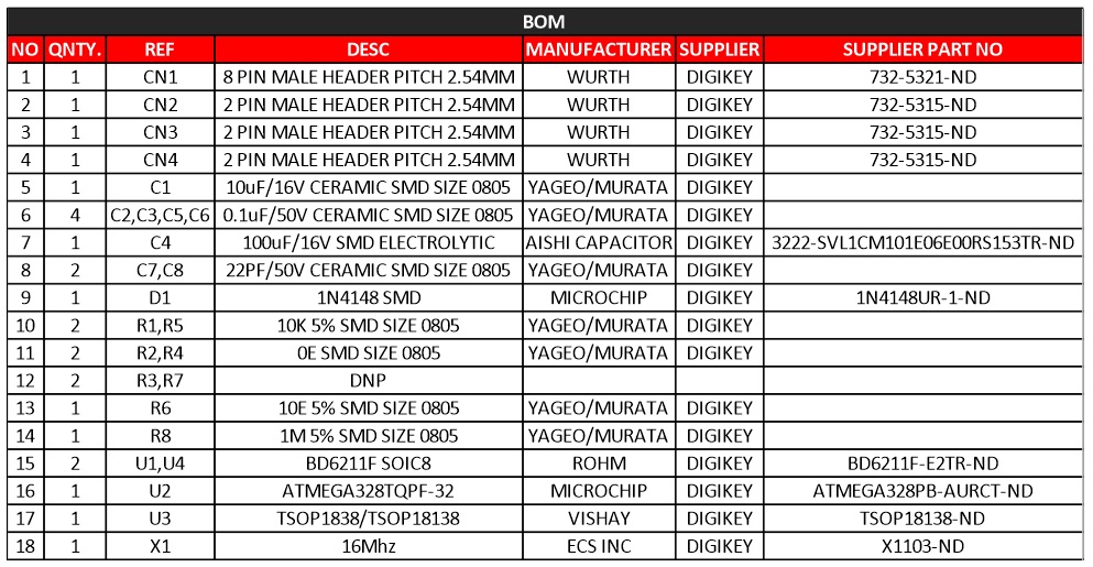
Parts List
| NO | QNTY. | REF | DESC | MANUFACTURER | SUPPLIER | PART NO |
|---|---|---|---|---|---|---|
| 1 | 1 | CN1 | 8 PIN MALE HEADER PITCH 2.54MM | WURTH | DIGIKEY | 732-5321-ND |
| 2 | 1 | CN2 | 2 PIN MALE HEADER PITCH 2.54MM | WURTH | DIGIKEY | 732-5315-ND |
| 3 | 1 | CN3 | 2 PIN MALE HEADER PITCH 2.54MM | WURTH | DIGIKEY | 732-5315-ND |
| 4 | 1 | CN4 | 2 PIN MALE HEADER PITCH 2.54MM | WURTH | DIGIKEY | 732-5315-ND |
| 5 | 1 | C1 | 10uF/16V CERAMIC SMD SIZE 0805 | YAGEO/MURATA | DIGIKEY | |
| 6 | 4 | C2,C3,C5,C6 | 0.1uF/50V CERAMIC SMD SIZE 0805 | YAGEO/MURATA | DIGIKEY | |
| 7 | 1 | C4 | 100uF/16V SMD ELECTROLYTIC | AISHI CAPACITOR | DIGIKEY | 3222-SVL1CM101E06E00RS153TR-ND |
| 8 | 2 | C7,C8 | 22PF/50V CERAMIC SMD SIZE 0805 | YAGEO/MURATA | DIGIKEY | |
| 9 | 1 | D1 | 1N4148 SMD | MICROCHIP | DIGIKEY | 1N4148UR-1-ND |
| 10 | 2 | R1,R5 | 10K 5% SMD SIZE 0805 | YAGEO/MURATA | DIGIKEY | |
| 11 | 2 | R2,R4 | 0E SMD SIZE 0805 | YAGEO/MURATA | DIGIKEY | |
| 12 | 2 | R3,R7 | DNP | |||
| 13 | 1 | R6 | 10E 5% SMD SIZE 0805 | YAGEO/MURATA | DIGIKEY | |
| 14 | 1 | R8 | 1M 5% SMD SIZE 0805 | YAGEO/MURATA | DIGIKEY | |
| 15 | 2 | U1,U4 | BD6211F SOIC8 | ROHM | DIGIKEY | BD6211F-E2TR-ND |
| 16 | 1 | U2 | ATMEGA328TQPF-32 | MICROCHIP | DIGIKEY | ATMEGA328PB-AURCT-ND |
| 17 | 1 | U3 | TSOP1838/TSOP18138 | VISHAY | DIGIKEY | TSOP18138-ND |
| 18 | 1 | X1 | 16Mhz | ECS INC | DIGIKEY | X1103-ND |
Connections
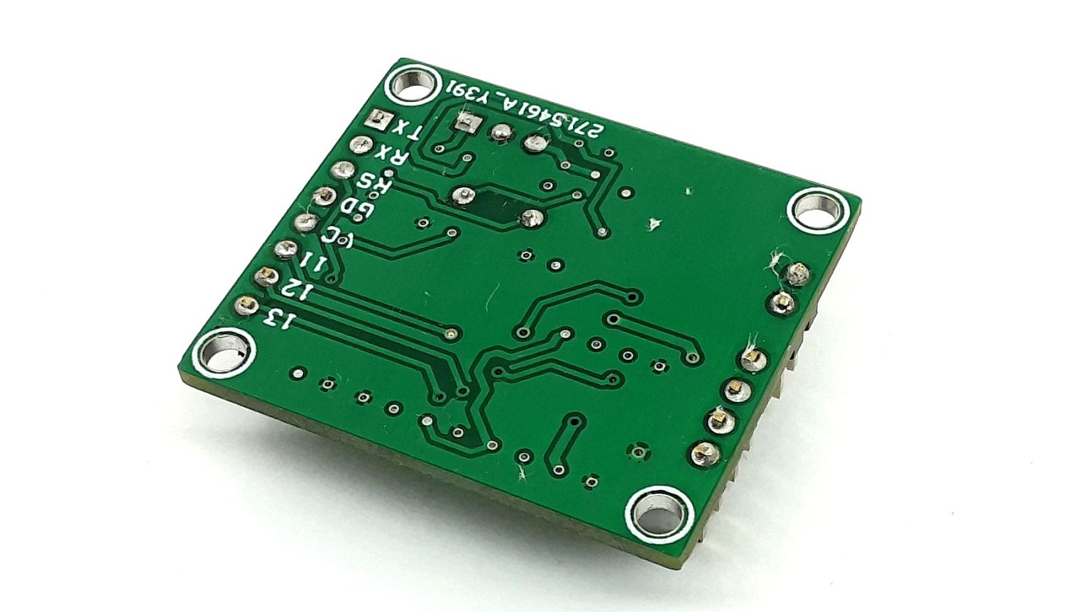
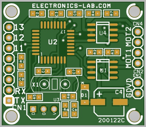
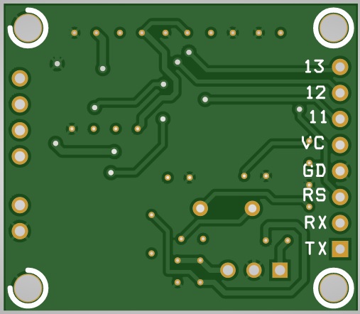
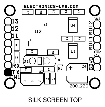
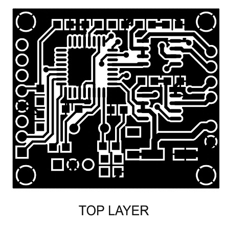
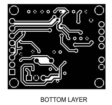
Gerber View
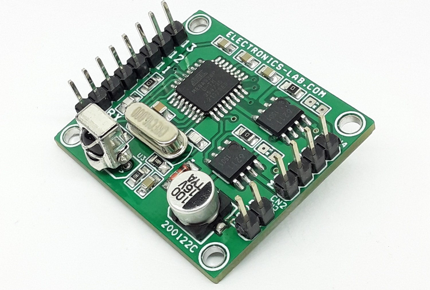
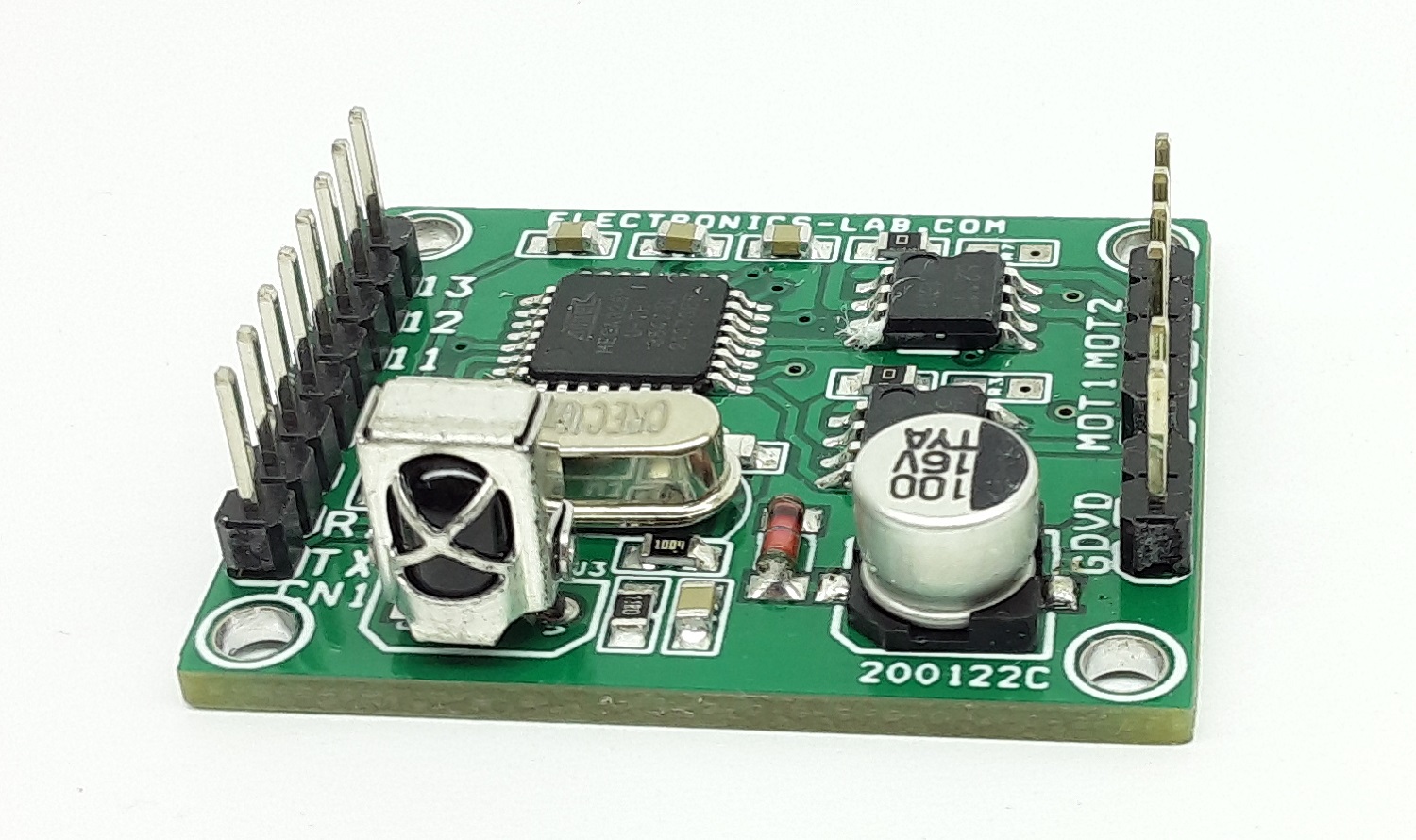
Photos
Video
TSOP1838 Datasheet
Please follow and like us:
PCB


Subscribe
Login
0 Comments


