MCS08DZ60 Evaluation Board
- Joel Guittet
- myfreescalewebpage@free.fr
- 5.541 Views
- medium
- Non tested
Introduction
The board shown in this article is build around a recent microcontroller from Freescale. It has some interesting features presented below, and is initially developed to learn with the CAN bus. It is an easy to build board particularly adapted for beginners.
The Microcontoller
The microcontroller used is the 68HCS08DZ60, from Freescale, and coming with an LQFP32 package. It is initially a microcontroller designed for automotive applications. It has some very interesting features:
- 60Ko of Flash memory;
- 4Ko of RAM;
- 2Ko of EEPROM ;
- Integrated CAN bus controller;
- Integrated SCI controller with LIN capability;
- Integrated I2C controller;
- Integrated SPI controller;
- Analog inputs, with a resolution of 12bits;
- Timers which can generated PWM signals;
- And more…
The Board
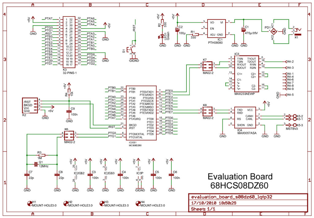
Please, see the schematic of the board.
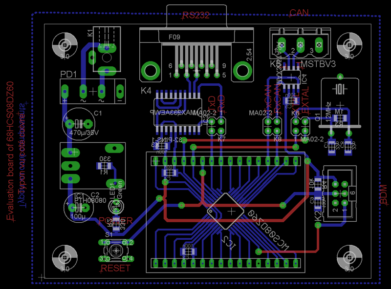
The board has been initially developed to learn with CAN, so a CAN transceiver is available (IC4). The CAN transceiver comes from Maxim, but some other manufacturers provide some compatible CAN transceivers which can be used. An RS232 transceiver is also mounted on the board to get an RS232 interface, to connect the board to a computer. It could be used for debug purpose for example. Both transceivers are connected to the microcontroller throw jumpers, so it is possible to disconnect the transceivers and use the pin of the microcontroller as classical GPIOs. The other parts of the schematic are not so special, we can found:
- The power supply, build around a DC/DC converter (IC1 ; a classical linear voltage regulator like 7805 can also be used without any modification of the PCB);
- A LED to indicate that the board is supplied (LED1);
- A switch connected on the RESET pin of the microcontroller (S1);
- The crystal (Q1). Note that the crystal is connected to the microcontroller throw jumpers: the device can work with an internal clock and in this case, the pins are available as classical GPIOs.
- Finally, there are some decoupling capacitors for all integrated circuits.
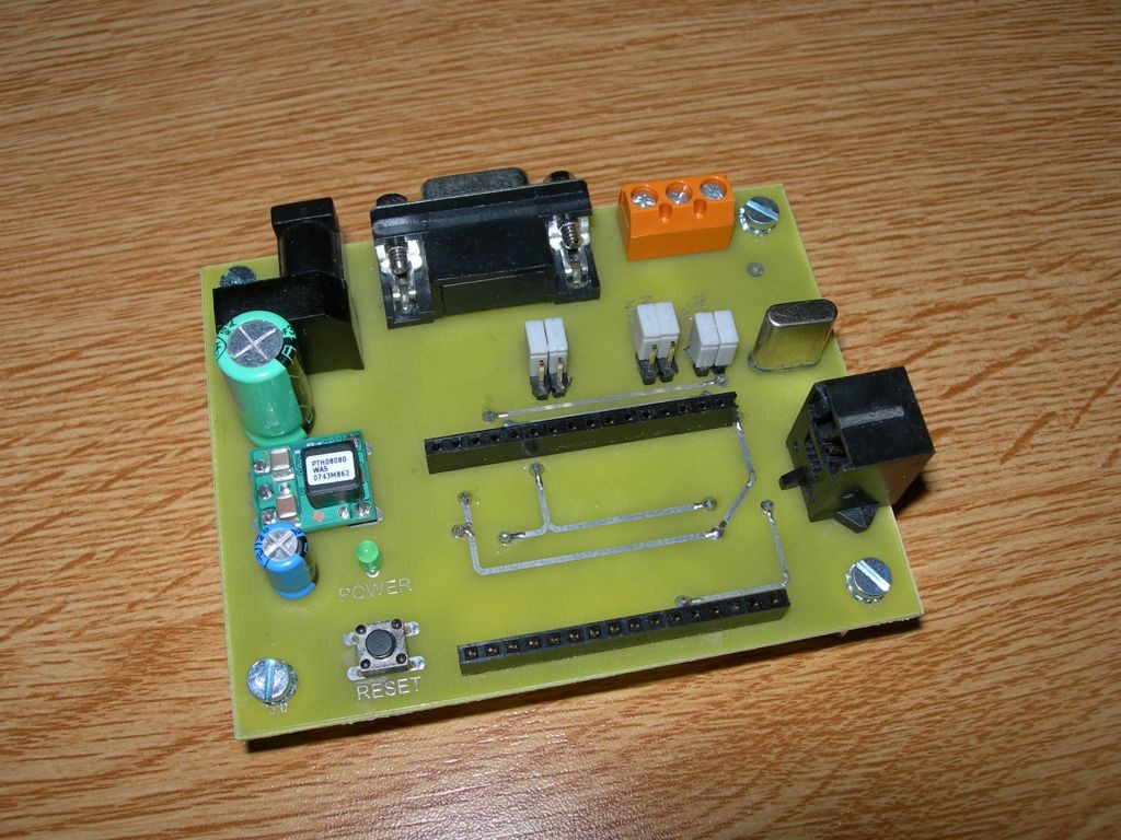
The power of the board will be applied on K1. Any power supplied can be used if it provided between 8 to 12 Volts AC or DC. K2 will be used to connect the programming cable, and K3 gives an access to all the pins of the microcontroller. K3 is build with two arrays of connectors to plug a module on the evaluation board (see photo #1).
Programming the microcontroller
To program the microcontroller, you will need a programming cable for Freescale HCS08 devices and you will have to download CodeWarrior for Microcontrollers from Freescale Web Site. Open source debugging cable and examples to begin with this board (CAN, 1-Wire, I²C, EEPROM …) are shown on my Web Site: http://myfreescalewebpage.free.fr
Conclusion
This small evaluation board is easy to build and will enable lots of experimentations. I have make two boards in order to create a small network throw the CAN interface. Of course this board is also interesting if you want to develop application around I²C, SPI, SCI… Remember that the peripherals available on the 8bits devices from Freescale are the same than on the 16 and 32bits devices, like the Coldfire for example. It is why this board is maybe the best way to start programming and learning with Freescale devices.


